Front and rear panels, S5500-28c-ei&s5500-28c-ei-dc – H3C Technologies H3C S5500 Series Switches User Manual
Page 12
4
Item
S5500-28C-PWR-EI
S5500-52C-PWR-EI
PoE model
PoE+ model
PoE model
PoE+ model
Relative humidity
(noncondensing)
10% to 90%
CAUTION:
•
Only the recommended RPS can be used for the RPS receptacles on S5500-EI Switch Series. The –48
VDC in the equipment room cannot be used directly. Otherwise, the device might be damaged.
•
For more information about the RPS power supply units, see the RPS user manuals and
RPS Ordering
Guide for H3C Low-End Series Ethernet Switches.
Front and rear panels
S5500-28C-EI&S5500-28C-EI-DC
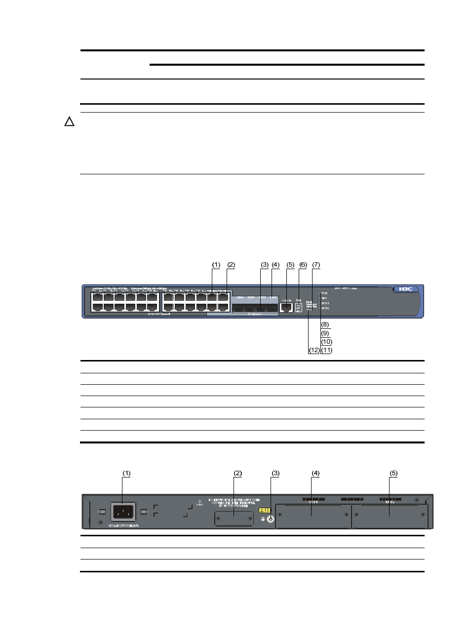
Figure 1 Front panel of the S5500-28C-EI&S5500-28C-EI-DC switch
(1) 10/100/1000 Base-T auto-sensing Ethernet port
(2) 10/100/1000 Base-T auto-sensing Ethernet port status LED
(3) 1000 Base-X SFP port
(4) 1000Base-X SFP port status LED
(5) Console port
(6) Seven-segment LED
(7) Port mode LED (Mode)
(8) System status LED (PWR)
(9) RPS status LED (RPS)
(10) Interface card 1 status LED (MOD1)
(11) Interface card 2 status LED (MOD2)
(12) Port status LED mode switching button
Figure 2 Rear panel of the S5500-28C-EI switch
(1) AC power input
(2) RPS power input (shipped with a protective cover)
(3) Grounding screw
(4) Interface card slot 1 (MOD1)
(5) Interface card slot 2 (MOD2)