Introduction to mounting bracket – H3C Technologies H3C S5500 Series Switches User Manual
Page 34
26
Introduction to mounting bracket
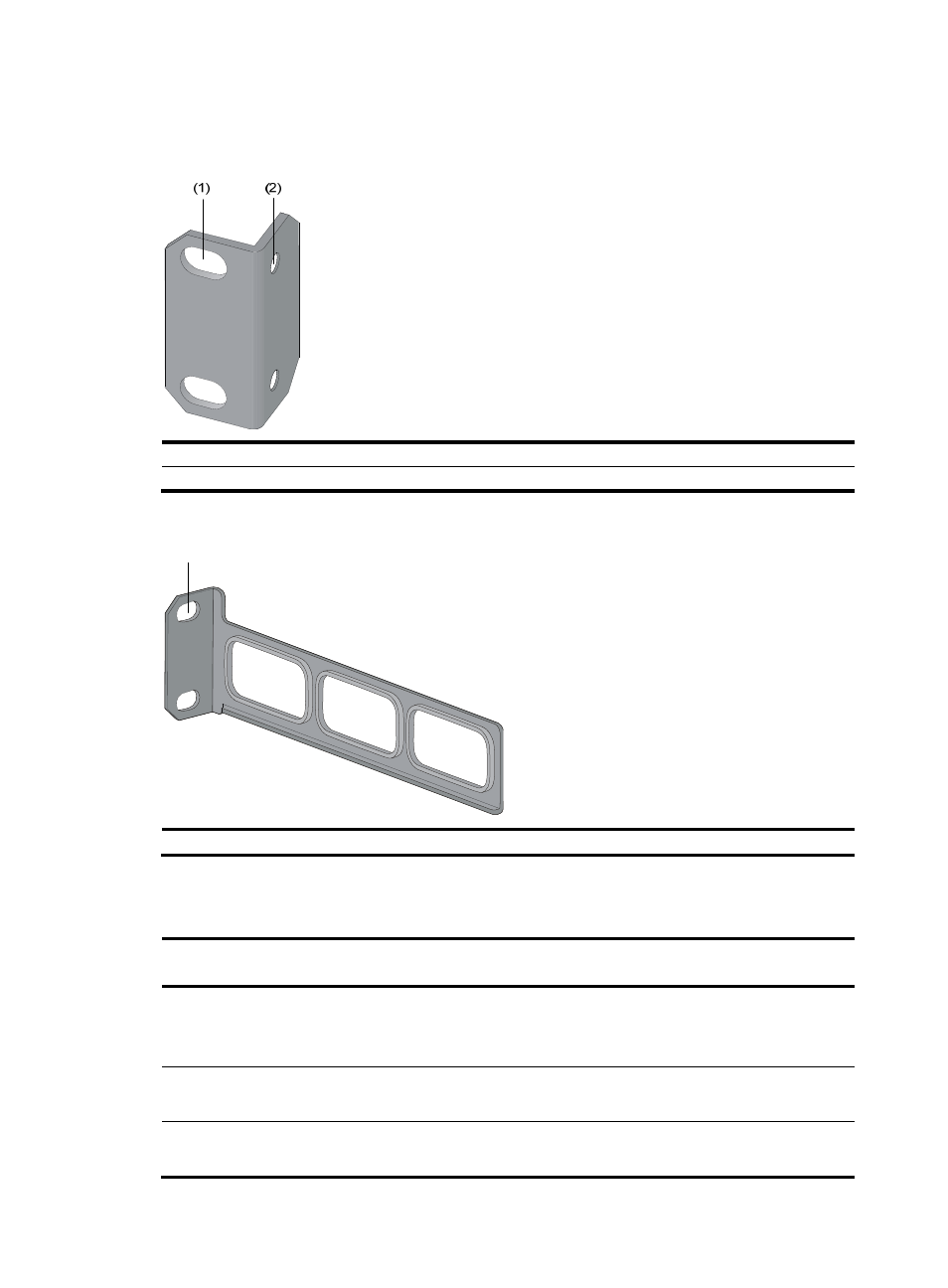
Figure 17 Appearance of a standard front mounting bracket
(1) Screw hole for attaching the mounting bracket to the cabinet (Use one M6 screw)
(2) Screw hole for attaching the switch to the mounting bracket
Figure 18 Appearance of a rear mounting bracket
(1) Screw hole for attaching the mounting bracket to the cabinet (Use one M6 screw)
For the selection of front and rear mounting brackets, see
.
Table 26 Selection of mounting bracket for the S5500-EI Switch Series
Model
Dimensions (H × W × D)
Configuration type of
front mounting bracket
Configuration type of
rear mounting bracket
S5500-28C-EI
S5500-52C-EI
S5500-28C-EI-DC
43.6 × 440 × 300 mm
(1.72 × 17.32 × 11.81 in) Standard N/A
S5500-28C-PWR-EI
S5500-52C-PWR-EI
43.6 × 440 × 420 mm
(1.72 × 17.32 × 16.54 in) Standard Standard
S5500-28F-EI
43.6 × 440 × 360 mm
(1.72 × 17.32 × 14.17 in)
Standard Standard
(1)
- H3C S12500X-AF Series Switches (3 pages)
- H3C S12500X-AF Series Switches (3 pages)
- H3C S12500X-AF Series Switches (53 pages)
- H3C S12500 Series Switches (19 pages)
- H3C MSV 50 (8 pages)
- H3C S12500 Series Switches (21 pages)
- H3C S9500E Series Switches (4 pages)
- H3C S7500E Series Switches (3 pages)
- H3C WA2200 Series WLAN Access Points (42 pages)
- H3C S12500-X Series Switches (8 pages)
- H3C SR6600 (64 pages)
- H3C S9500E Series Switches (36 pages)
- H3C WA3600 Series Access Points (237 pages)
- H3C S9500E Series Switches (270 pages)
- H3C MSR 900 (249 pages)
- H3C S12500 Series Switches (163 pages)
- H3C S12500 Series Switches (170 pages)
- H3C MSR 900 (96 pages)
- H3C MSR 900 (443 pages)
- H3C MSR 900 (468 pages)
- H3C S9500E Series Switches (32 pages)
- H3C S9500E Series Switches (241 pages)
- H3C S12500 Series Switches (39 pages)
- H3C S6800 Series Switches (59 pages)
- H3C LSBM1WCM2A0 Access Controller Module (197 pages)
- H3C S10500 Series Switches (27 pages)
- H3C LSBM1WCM2A0 Access Controller Module (226 pages)
- H3C S6300 Series Switches (188 pages)
- H3C MSR 900 (410 pages)
- H3C MSR 900 (239 pages)
- H3C WA3600 Series Access Points (394 pages)
- H3C S10500 Series Switches (2 pages)
- H3C S10500 Series Switches (2 pages)
- H3C S10500 Series Switches (2 pages)
- H3C S10500 Series Switches (2 pages)
- H3C S10500 Series Switches (2 pages)
- H3C S10500 Series Switches (2 pages)
- H3C S10500 Series Switches (2 pages)
- H3C S10500 Series Switches (1 page)
- H3C S7500E Series Switches (19 pages)
- H3C S7500E Series Switches (115 pages)
- H3C S6300 Series Switches (58 pages)
- H3C S6300 Series Switches (208 pages)
- H3C S6300 Series Switches (251 pages)
- H3C S10500 Series Switches (140 pages)