Setting the operating mode to irf mode, Figure 12, Figure 13 – H3C Technologies H3C S12500 Series Switches User Manual
Page 28
20
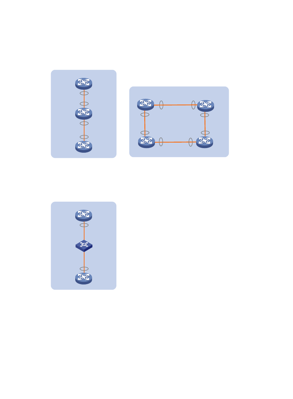
Connect the devices into a daisy chain topology or a ring topology. A ring topology is more reliable
(see
).In ring topology, the failure of one IRF link does not cause the IRF fabric to split as in daisy
chain topology. Instead, the IRF fabric changes to a daisy chain topology without interrupting network
services.
Figure 12 Daisy chain topology vs. ring topology
If two IRF member devices are far away from each other (for example, if they are in different cities), you
can use a relay device to connect them, as shown in
.
Figure 13 Daisy chain topology with a relay
Setting the operating mode to IRF mode
By default, the device is operating in standalone mode. To assign the device to an IRF fabric, you must
change its operating mode to IRF mode.
Before changing to IRF mode, use the display irf configuration command to verify that a member ID has
been assigned to the device. If the MemberID field displays two hyphens (--), first assign a member ID to
the device.
IRF
Ring connection
Subordinate
Subordinate
Master
IRF-Port1
IRF-Port2
IRF-Port1
IRF-Port2
IRF-Port1
IRF-Port2
Daisy chain connection
IRF
Master
Subordinate
Subordinate
IRF-Port2
IRF-Port2
IRF-Port1
IRF-Port1
Subordinate
IRF-Port2
IRF-Port1
Daisy chain topology with a relay
IRF
Master
Subordinate
IRF-Port2
IRF-Port1
Relay