Ensemble Designs 6040 Tracking Audio Delay User Manual
Page 14
Internal Jumper and Indicators
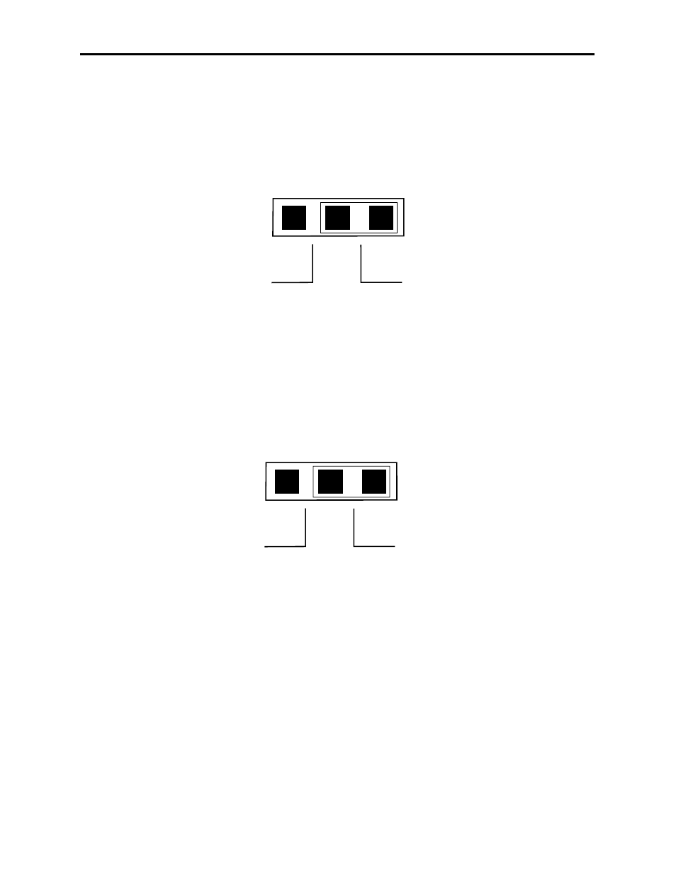
Analog Input Gain Bypass Jumpers:
Jumpers J5 and J6 are set at the factory but can be used to bypass the module's analog
input gain cell if needed for troubleshooting purposes. J5 is used for channel 1 and J6 is
used for channel 2. The following diagram shows the two possible selections
When gain cells are bypassed the reference level is set to a nominal level of +4 dBu. Make
sure the Analog Input jumpers are always set to Enable for normal operation.
Analog Output Jumpers:
Jumpers J7 and J8 are set at the factory but can be used to bypass the modules analog
output gain cells for troubleshooting purposes if needed. J7 is used for channel 2 and J8 is
used for channel 1. The following diagram shows the two possible selections.
When gain cells are bypassed the reference level is set to a nominal level of +4 dBu. Make
sure the Analog Output jumpers are always set to Enable for normal operation.
DSP LED
The 6040 has an internal LED (D14) that is used to indicate the state of the DSP. The two
indicated states are as follows:
•
Steady State – If the LED is at a steady state of either ON or OFF then the DSP
is not running. Reset the module to if this has occurred to try to get the DSP
running. If resetting the module will not fix the problem, contact customer support.
•
Flashing State – Indicates that the DSP is running normally. Refer to the
Ref/Stat heading in the Avenue PC or Touch Screen sections for more information
regarding the DSP.
Model 6040 Tracking Audio Delay
Front of Module
Rear of Module
Jumper to Bypass
Gain Cell
Jumper to Enable
Gain Cell
J5 and J6
Analog Input Jumpers
Front of Module
Rear of Module
Jumper to Bypass
Gain Cell
Jumper to Enable
Gain Cell
J7 and J8
Analog Output Jumpers
Analog Input Jumpers J5 and J6
Analog Output Jumpers J7 and J8
6040-14