Ensemble Designs 5400 Dual Sync Generator and Test Signal Generator with HD Tri-Level Sync User Manual
Page 8
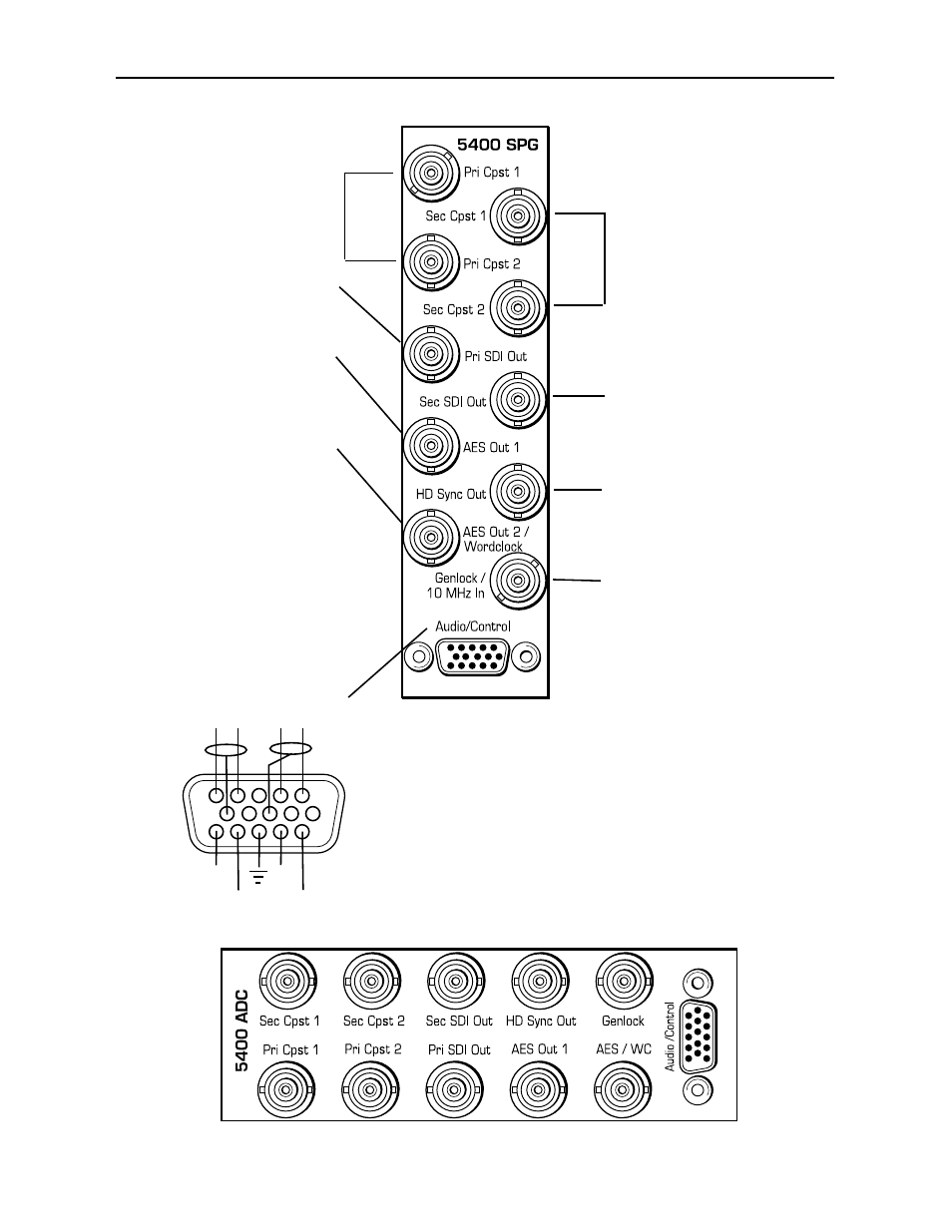
Model 5400 Dual Sync Gen/Test Signal Generator
3 RU Backplane
Connect the Pri Cpst 1
and Pri Cpst 2 output
BNCs to composite
analog destinations.
Connect the Sec Cpst 1
and Sec Cpst 2 output
BNCs to composite
analog destinations.
Connect the Pri SDI Out
BNC to a serial digital
destination.
Connect the AES Out 1
BNC an AES audio desti-
nation. (5410 submodule
required.)
Connect the AES Out 2/
Wordclock BNC to an AES
audio or wordclock destina-
tion (5410 submodule
required).
NOTE: To enable the
Wordclock output, jumper J3
on the 5410 submodule must
be set to WD_CLK. Use the
Pulse Select pulldown in the
Config menu to set the pulse
type to Wordclock or a 6 Hz
pulse.
5400-8
Connect the Sec SDI
Out BNC to a serial
digital destination.
Connect the HD Sync
Out BNC to a high defi-
nition destination.
Connect an NTSC/PAL or 10
MHz input signal to the
Genlock/10 MHz In BNC to
provide the external genlock
reference.
1
6
+
-
11
CH A
+
-
GPI
1
GPI
2
GPI
3
GPI
4
CH B
With the 5410 submodule installed, you can access the CH A
and CH B analog tone outputs according to the pinout at left.
You may connect an external device to the GPI inputs at pins
11, 12, 14 and 15 of the Audio Out connector to remotely
control one of four slates.
There are two channels of audio. Channel A is on pins 1 and
2 and the associated ground is pin 8. Pin 1 is positive.
Channel B is on pins 4 and 5 and the associated ground is on
pin 10. Pin 5 is positive.
1 RU
Backplane