Ensemble Designs 5400 Dual Sync Generator and Test Signal Generator with HD Tri-Level Sync User Manual
Page 7
5410 Submodule
Install the 5410 submodule by lining up the connectors on the submodule with the connec-
tors on the 5400 module. The connector is keyed to prevent installing it incorrectly.
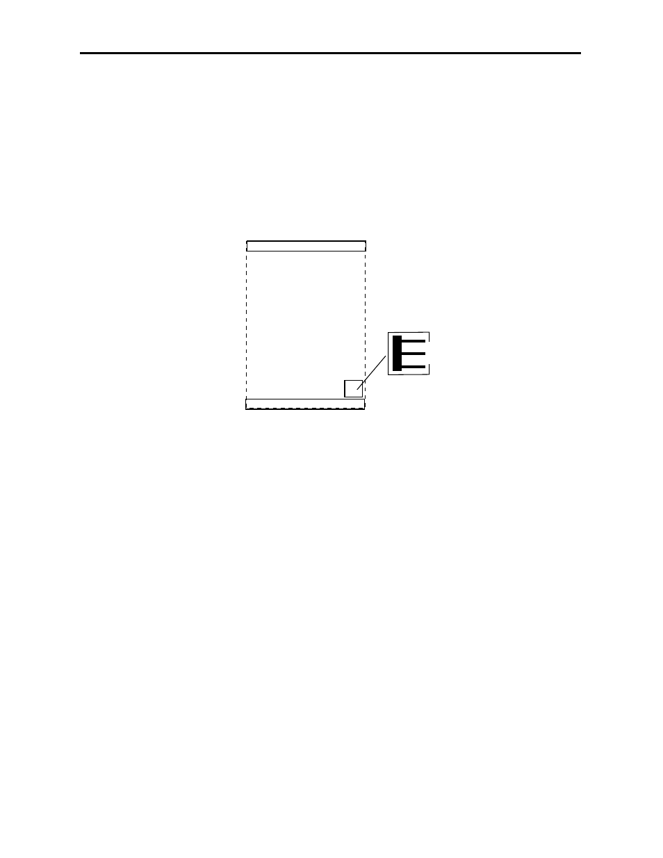
AES B Out Jumper
A jumper, AES B OUT, J3, on the 5410 submodule (shown below) allows the user to select
the type of audio output on the AES Out 2/Wordclock BNC on the rear of the module.
When AES is selected, the output will be an AES3id signal from the BNC. Setting J3 to
WD_CLK, allows either a Wordclock output or a 6 Hz 4.5 align pulse, used in telecine
applications. When set to WD-CLK, the pulse type must be selected in the Pulse Select
pulldown in the Avenue PC or Touch Screen Config menu.
5400 Module
Plug the 5400 module into any one of the slots in the 3 RU frame and any slot except Slot
3 in the 1 RU frame. Install the plastic overlay provided onto the corresponding group of
rear BNC connectors associated with the module location. Note that the plastic overlay
has an optional adhesive backing for securing it to the frame. Use of the adhesive backing
is only necessary if you would like the location to be permanent and is not recommended if
you need to change module locations. This module may be hot-swapped (inserted or
removed) without powering down or disturbing performance of the other modules in the
system.
CABLING
Refer to the 3 RU and 1 RU backplane diagrams of the module on the next page for
cabling instructions. Note that unless stated otherwise, the 1 RU cabling explanations are
identical to those given in the 3 RU diagram.
Model 5400 Dual Sync Gen/Test Signal Generator
5410 Submodule
J3 AES B OUT
WD_CLK
AES
5400-7
5410 Jumper Setting