Ericsson LBI-39224 User Manual
Page 240
LBI-39224
4-2
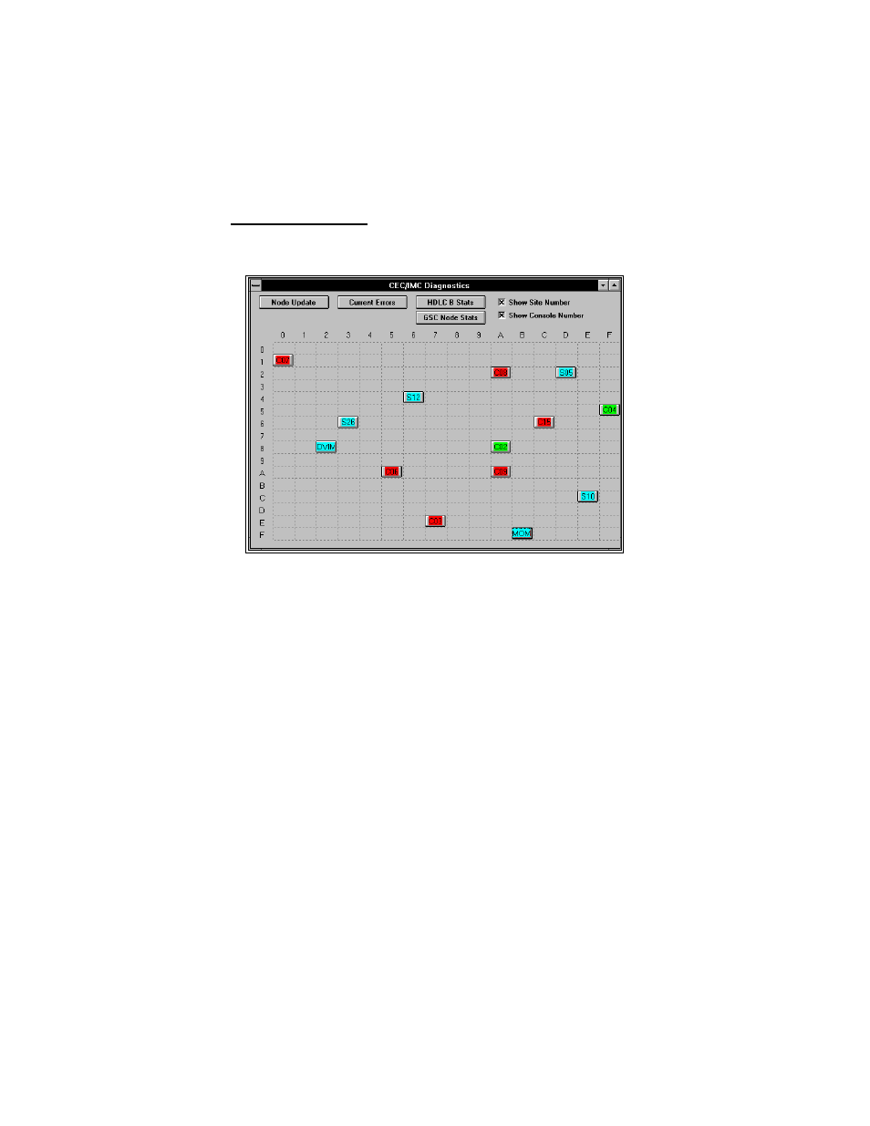
4.2.1 Node Matrix
The Node Matrix screen contains a 16 x 16 matrix of all possible
hexadecimal GSC node addresses in the system.
Figure 45 CEC/IMC Diagnostics (Node Matrix) Screen
Press the F1 key to access the Help function.
The available addresses are the range 00h to EFh and FBh, which is the
permanent address of the MOM Controller Board. F0h thru FAh and
FCh thru FFh are reserved and cannot be accessed. Each installed
device in the system is represented by a colored "node" with the device
type displayed on the node. The meaning of the node colors are as
follows:
–
Blue - the device Link State is UP
–
Red - the device has a failed Control Link
–
White - the device Link State is UP, but other errors exist
– Yellow - the device (MIM or NIM) is active but the
corresponding site is in a Failsoft condition
–
Green - indicates that the device is a CIM and that the CIM is
active with Link State UP