Allmand Brothers MB 6200 User Manual
Page 45
45
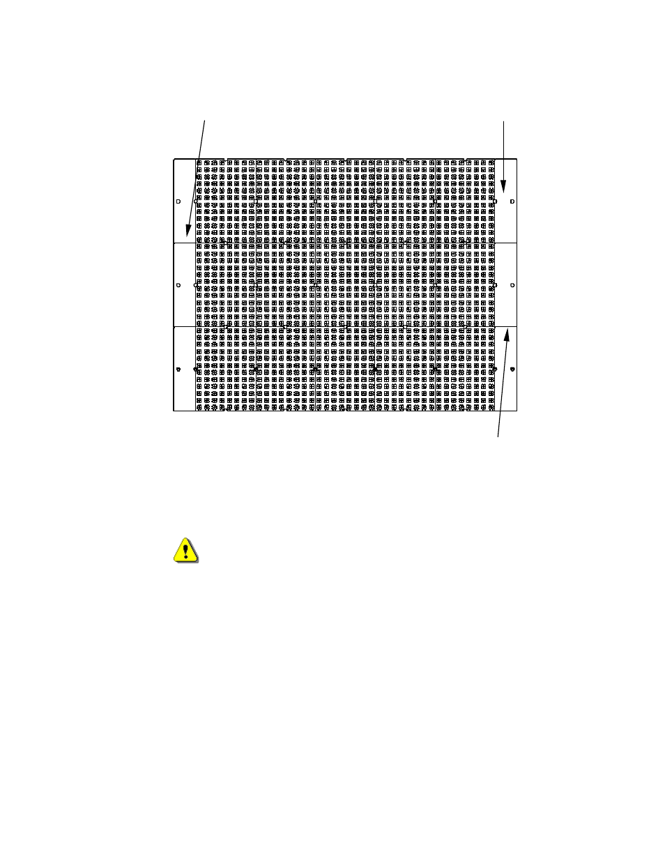
Figure 20. Full Matrix Sign, 5
×
3—Vertical Orientation—Completed Sign
Failure to follow the lock down procedure correctly may result
in loose or fallen BRICKs. Make sure that the locking foot is
inserted and rotated 90 degrees clockwise.
Caution
15. For Odd numbered rows, begin with the locking foot in the three o’clock position. Install the hold-down
lock through the hole between BRICKs (see figure 21). Using the lock tool, press down to engage the
lock about 1/4-inch (64 mm) until the lock bottoms on the rail assembly. Turn 1/4-turn clockwise and
release the tool. The lock mechanism should remain inside the hold-down lock body.
16. For Even numbered rows, begin with the locking foot in the nine o’clock position. Install the hold-
down lock through the hole between BRICKs (see figure 22). Using the lock tool, press down to
engage the lock about 1/4-inch (64 mm) until the lock bottoms on the rail assembly. Turn 1/4-turn
clockwise and release the tool. The lock mechanism should remain inside the hold-down lock body.
Right Jumper BRICK Assembly
Left Jumper BRICK Assembly
Trim BRICK