Allmand Brothers MB 6200 User Manual
Page 13
13
Explanation of some BRICK operating current conditions described in previous table:
Power Supply Rating – Amount of power (Watts) needed per BRICK. This is a general rule of thumb to
allow for the potential of powering all LED pixels at full brightness.
Average 24-Hour Current – Current draw over 24 hour day (assume 12 hours daytime, 12 hours nighttime)
with an average text based display that utilizes approximately 30% of the LEDs pixels for High Density
BRICKs, 40% LEDs for Standard Density BRICKs.
Absolute Maximum Current – Current limit setting on a BRICK resulting in the worst case current draw in
the event of a failure.
Typical Maximum Current – Current draw for a BRICK in maximum ambient light conditions with all of the
pixels lit.
See also
Connecting Power in Assembling and Installing a Message Sign section for additional informa-
tion regarding BRICK system power source requirements.
Rail Assembly
The rail assembly consists of the following:
•
Aluminum housing with mounting holes, grooves and flanges — for housing conductors and conductor
insulation as well as mounting to sign support system.
•
Conductor (bus bar)
•
Conductor insulation
The rail assembly:
•
Carries both the 12V dc power and the communications data to each BRICK.
•
Eliminates the need for character-to-character wiring, terminal blocks, connectors, and solder joints.
•
Acts as a support for the BRICKs.
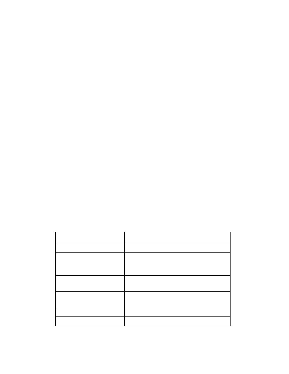
Rail assembly information and details are summarized in the following table:
Rail Information
Details
Rail housing material
Aluminum, painted black powder coat
Conductor material
Copper alloy, metal plating; 0.062 by
1.0in.(0.15 by 2.54cm), cut to match rail
housing; strip fits into insulator
Insulator material
Vinyl, cut to match rail housing; fits in
grooves in rail housing
Length (rail housing)
240 in. (609.6 cm) maximum: cut for
shorter lengths
Width (rail housing)
5 in. (12.7cm)
Depth (rail housing)
0.6 in (1.5cm)