Installation, cont’d, Preliminar y, Caution – Extron Electronics Extender Series User Manual
Page 20: Extender series • installation, Audio unbalanced output, Balanced output, Power, Do not tin the wires
Extender Series • Installation
Installation, cont’d
2-10
PRELIMINAR
Y
a
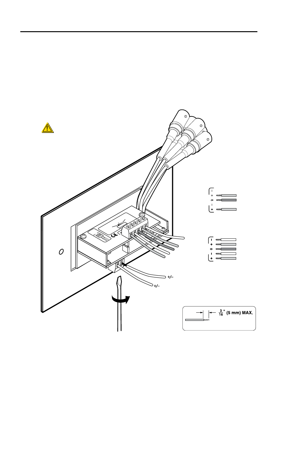
Audio output connector — Insert wires into and tighten the
screws on this 3.5 mm, 5-pole direct insertion captive screw
connector for unbalanced or balanced audio output. Wire the
connector as shown in the following illustrations.
C
Connect the sleeve to ground (Gnd). Connecting the
sleeve to a negative (-) terminal will damage the audio
output circuits.
Ex
ten
der
Se
rie
s
9-1
8 V
DC
Po
wer
Gain
(Sw
itch
is
on
the
low
er
circ
uit
boar
d.)
Ma
xim
um
Ma
x. p
eak
ing
& g
ain
Me
diu
m
– M
id-le
vel
pea
kin
g &
ga
in
No
rm
al
Un
ity
gain
ww
w.e
xtro
n.c
om
33-
612
-02
Re
v. C
02
05
L
Au
dio
R
Audio
Unbalanced Output
Left Tip
NO Ground Here
Sleeve (s)
Right Tip
NO Ground Here
Balanced Output
Sleeve (s)
Left Tip
Right Tip
Left Ring
Right Ring
Sleeve (s)
Left Tip
Right Tip
Left Ring
Right Ring
L
A
u
di
o
R
L
A
u
dio
R
9-18 VDC
Power
CAUTION
For unbalanced audio, connect the
sleeve(s) to the ground contact.
DO NOT
connect the sleeve(s)
to the negative (-)
contacts.
Do not tin the wires!
Extender WM AUS is shown here wired for balanced
audio output; the circuit board configuration is the same
for the Extender MK, Extender AAP, Extender AAP EX,
Extender AKM UK AAP, and Extender AKM MAAP