5 high level control (hlc) – Watson-Marlow DuCoNite 25 User Manual
Page 24
INSTALLATION
24
•
All control cables outside the enclosure must be
shielded and have a cross sectional area
between 0.22 and 1 mm
2
. The shielding must
be connected to earth at both ends.
5.3.5
High Level Control (HLC)
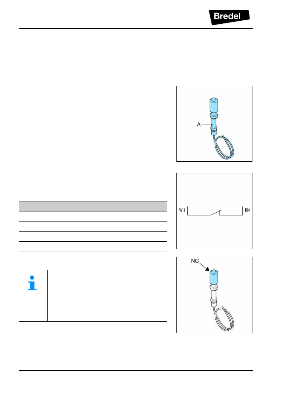
To sense the lubricant level inside the pump housing the
pump is provisioned with a floater. The HLC floater (A)
is positioned above the normal lubricant level of the
pump. When a hose fails, the product will be pressed
into the pump casing and causes a level rise of the
lubricant. The HLC shall detect this rise of lubricant.
After hose failure, the floater needs to be cleaned.
Connection of floaters:
The floater has to be connected to the auxiliary power
circuit via the 1 meter long PVC cable (2 x 0.24 mm
2
).
Specifications
Scope:
For use in non-explosive environments
Voltage:
Max. 230 V AC/DC
Current:
Max. 1 A
Power:
Max. 50 VA
Where the floater is constructed to stop the
equipment, operating has to be arranged
so that the stop function locks-out, prevent-
ing the equipment from being re-started
without re-setting. Check if the floater is
mounted with the NC sign at the top.