Quick set-up, Chapter – Verilink IMUX (880-503137-001) Product Manual User Manual
Page 15
Verilink IMUX User Manual
2-1
Chapter
2
Quick Set-Up
The Quick Set-Up section provides the steps necessary to install
and configure a typical IMUX configuration. Refer to the menu
options described in Chapter 3,
“Configuration Menus”
when
determining the settings and values for your configuration.
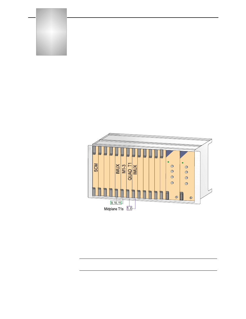
The following assumptions are used in the example configuration
(
):
•
An SCM is in slot 1
•
An M1-3 multiplexer is in slot 6
•
IMUX modules are in slots 5 and 8
•
A QUAD T1 is installed in slot 7
Figure 2-1
Configuration Example Module Placement
The following midplane circuits are created in the circuit-build
example (
•
from QUAD T1 network ports 1 and 2, to the data port on the
IMUX in slot 8, which is supporting a router.
•
from M1-3, T1 ports number 9, 10, and 11, to the IMUX module
in slot 5 supporting a router.
NOTE: Adjust one or more of these values to adapt the quick set-up
to your configuration.
- 1061 T1 Multicast (34-00268) Product Manual (18 pages)
- 2010 (34-00204) Product Manual (15 pages)
- 1558A (34-00228) Product Manual (39 pages)
- 1558D (34-00255) Product Manual (42 pages)
- 210 (34-00196) Product Manual (9 pages)
- 2000 (34-00182) Product Manual (58 pages)
- 300 (34-00199) Product Manual (9 pages)
- 2048 (34-00179) Product Manual (33 pages)
- 400 (34-00222) Product Manual (9 pages)
- 2100 (34-00187) Product Manual (19 pages)
- 7200p Series IAD (34-00334.B) Product Manual (311 pages)
- APS 2000 T1 Line Protection (880-502411-001) Product Manual (87 pages)
- AS200 (896-502379-001) Product Manual (112 pages)
- AS420 (34-00294) Product Manual (28 pages)
- AS56/56Plus (896-502588-001) Product Manual (130 pages)
- 9000 Series (34-00271) Product Manual (440 pages)
- AS2000: The Basics (880-502981-001) Product Manual (179 pages)
- Access Manager 2000 (896-502037-001) Product Manual (400 pages)
- ConnecT 56K DSU (896-502110-001) Product Manual (88 pages)
- AS4000 (34-00244) Product Manual (210 pages)
- C150 (880-502893-001) Product Manual (135 pages)
- Craft Interface (No Part Number) Product Manual (8 pages)
- DDS Lite (34-00295.C) Product Manual (19 pages)
- DCSU 2911 (880-502647-001) Product Manual (79 pages)
- DIDCSU 2912 (880-502646-001) Product Manual (107 pages)
- DIU 2130 (880-503297-001) Product Manual (101 pages)
- DIU 2131 (880-502765-001) Product Manual (31 pages)
- FrameStart FSE (34-00291.F) Product Manual (49 pages)
- DPRI 2922 (880-503142-001) Product Manual (91 pages)
- HDM 2180 (880-503048-001) Product Manual (79 pages)
- HDM 2182 (880-502925-001) Product Manual (81 pages)
- FrameStart FSM (34-00299.E) Product Manual (153 pages)
- TAC 2010 (880-503298-001) Product Manual (65 pages)
- M1-3 (880-503136-001) Product Manual (75 pages)
- NCC 2130 (880-503285-001) Product Manual (61 pages)
- NCM 2000 (880-502623-001) Product Manual (91 pages)
- NetPath 2000 Product Manual (30 pages)
- PRISM 3000 (34-00184) Product Manual (45 pages)
- PRISM 3001 (34-00186) Product Manual (58 pages)
- PRISM 3002 (34-00277) Product Manual (52 pages)
- Net Engine (3150-30626-001) Product Manual (323 pages)
- PRISM 3021 (34-00262) Product Manual (47 pages)
- PRISM 3010 Dual DSX-1 (34-00250.2) Product Manual (22 pages)
- PRISM 3060-10 (34-00252.4) Product Manual (76 pages)