Triplett TVR10/100/1000 User Manual
Page 15
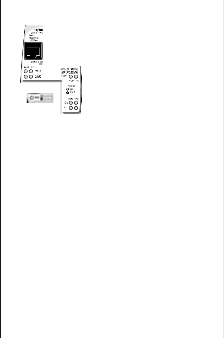
The TVR1000 must be ON before plugging in devices. Using the
two RJ45 straight thru patch cables provided with the TVR1000,
plug two LAN devices into the leftmost jacks (making a straight thru
connection between the two devices). Allow 3 seconds between
plugging in devices (the time it takes the TVR1000 to make a read-
ing). A reading is taken for each device and displayed across two
columns of LEDs. The device that appears as hub (or switch) has
its column of LEDs as does the device that appears as a PC. For
communication to exist, both columns must have a LED ON. If they
don't, move the cable plugged into the center jack to the jack on the
far right (making a crossover connection). Once both columns have
a LED lit, the devices are communicating and the required patch
cable has been determined. If only one column of LEDs comes ON
in either jack configuration a problem exists. Isolate the problem by
plugging one device at a time into the TVR1000’s GREEN Jack (the
left jack). The device that does not show any activity on the LEDs
is causing the problem. If it is the remote device that is showing no
activity, there may be nothing connected at the far end of the cable.
See “Cable Tests Jack” later in this section to test for a device on the
other cable end.
The LED definitions described on the opposite page (Single Port
13
Inline testing
Use the three jacks to determine the
negotiated speed and duplex between any
two LAN devices. The multiple jacks pro-
vide both a straight thru and a crossover
connection (if required).