Single point / flange facer – Tri Tool 212B Beveler Single Point Flange Facer User Manual
Page 9
9
92-0729 : Rev. 070928
212B BEVELMASTER
TM
SINGLE POINT / FLANGE FACER
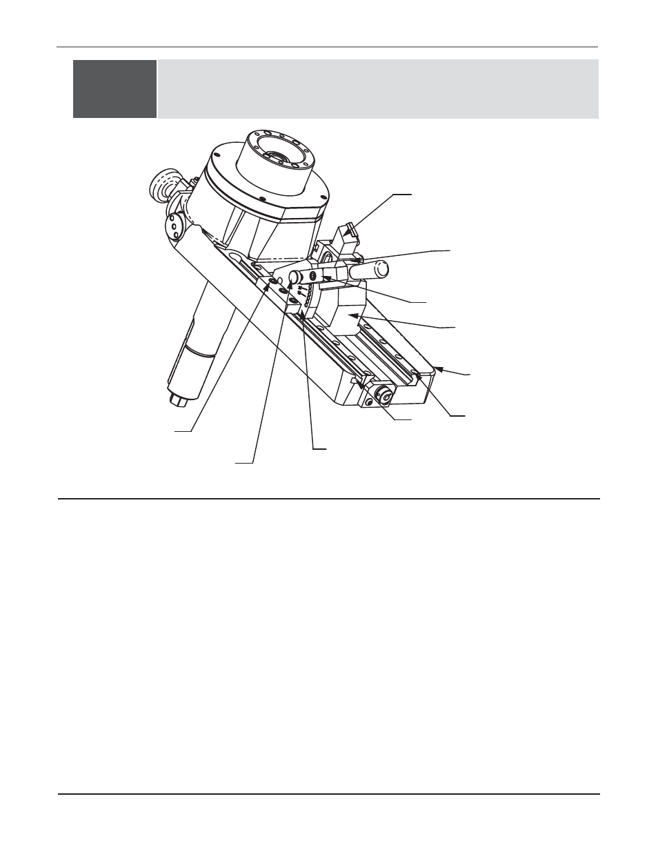
INSERT TOOL
HOLDER
CAM TRACK
PLATE
LOCK BLOCK
TOOL HOLDER
ASSEMBLY
ADJUSTMENT SET
SCREWS
SLIDE RAIL
RETAINING
CAP SCREWS
T-SLOT
CAM TRACK
PLATE ASSEMBLY
PLUNGER PIN
(3)CAP SCREWS
TOOL SLIDE ADJUSTMENT 212B SINGLE POINT
When To Adjust:
The tool slide does require adjustment more frequently when the tool is new
because of “break in”.
It is recommended that the slide be adjusted or checked for looseness
everyday, or after any long period of use.
If any unusual chatter occur, the tool slide could be one of the possible
sources of instability that produces chatter or a bad finish.
When ever the tool is to be lubricated or serviced.
Procedures:
To adjust the tool slide, remove the cam track plate assembly. To do so,
loosen the 3 cap screws in the “T” slot. Advance the tool holder assembly to
the opposite end of the boss. Loosen the lock block, pull back the plunger
pin, swing around the track plate and slide off the end of the main plate the
cam track plate assembly.
NOTE:
After the Mandrel Boss Assembly has been set once, it should not
need readjustment after removal or reinstallation. Readjustment may
be necessary for wear adjustment.
Parts of the Tool Holder Mechanism