Connections, fan speed control – TE Technology TC-720 User Manual
Page 25
If the fan only has two or three wires, it is likely not rated for PWM fan-speed control. If the fan is not rated for PWM
fan-speed control it should not be used in this configuration. Using PWM fan-speed control with a fan that is not
rated for it can damage the fan.
The default configuration for JP2-8 is to serve as ALARM1 output. The controller will need to be software
programmed (described in Section 4) for fan speed control rather than serving as ALARM1. ALARM2 may be
configured to sense the temperature from the Primary Sensor or the Secondary Sensor as required.
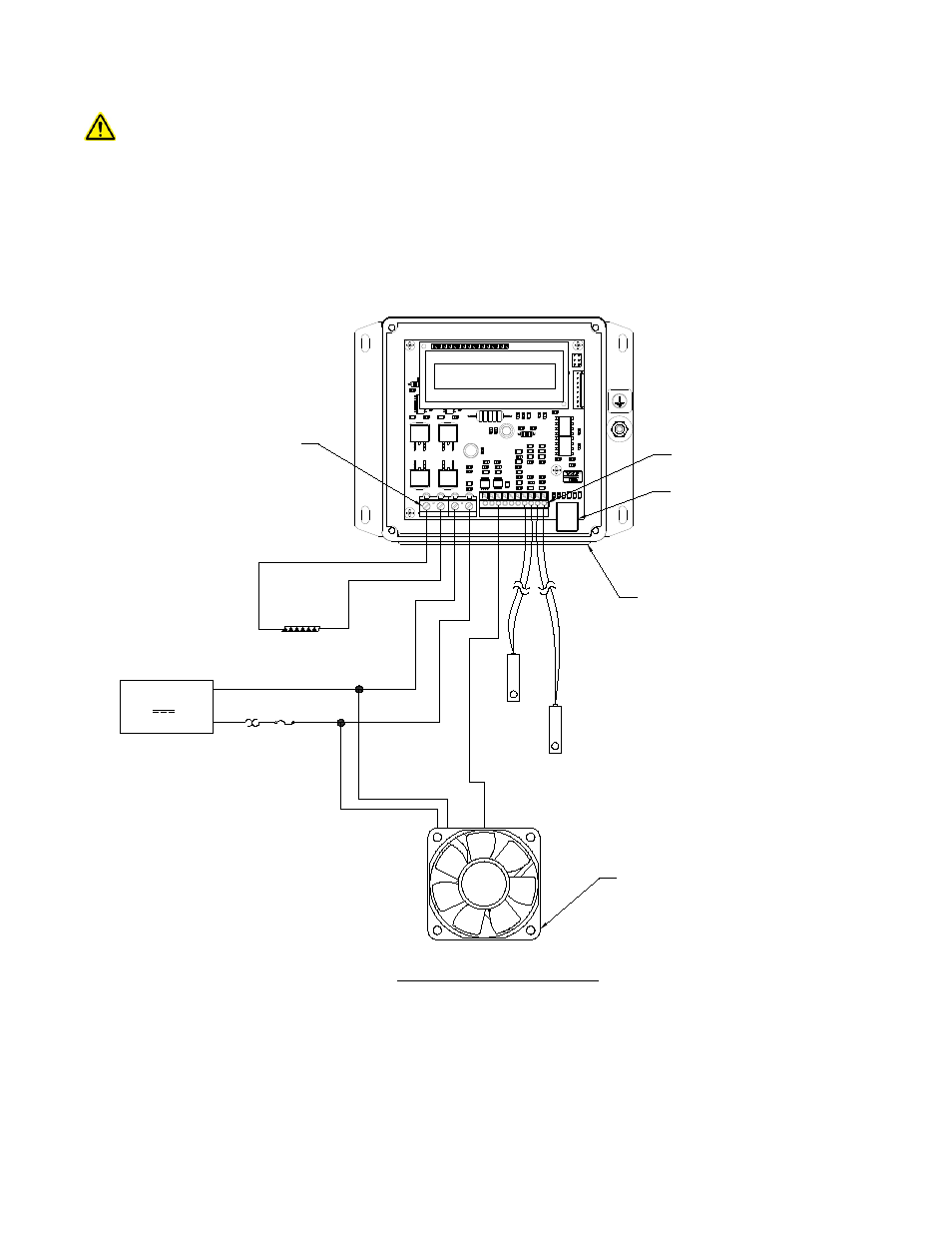
Connections, Fan Speed Control
(connections and components may vary depending on the fan being used)
JP7
JP2
1
2
3
4
10
9
8
7
6
5
4
3
2
1
(+)
(-)
TE DEVICE
DC
POWER SUPPLY
OPTIONAL FUSE
THERMOSTAT AND OTHER
PROTECTIVE DEVICES
(CUSTOMER SUPPLIED)
12 V, 36 V, 20 A maximum
JP7
PIN 1
JP2
PIN 1
WIRES MUST PASS THROUGH
GASKET HOLES
NOTE: LID IS REMOVED TO SHOW
WIRE CONNECTIONS
USB COMMUNICATION PORT
to JP7-1
to JP7-2
to JP7-3
to JP7-4
(+)
(-)
(+)
(-)
PWM FAN
to JP2-8
Consult fan manufacturer for
minimum allowable duty cylce
before fan stops spinning and
any other applicable
requirements.
PWM
OPTIONAL
SECONDARY
SENSOR
JP2-4 (+) and
JP2-3 (-)
CONTROL
SENSOR
JP2-1 (+) and
JP2-2 (-)
25