Connections, other applicable devices – TE Technology TC-720 User Manual
Page 24
1.5
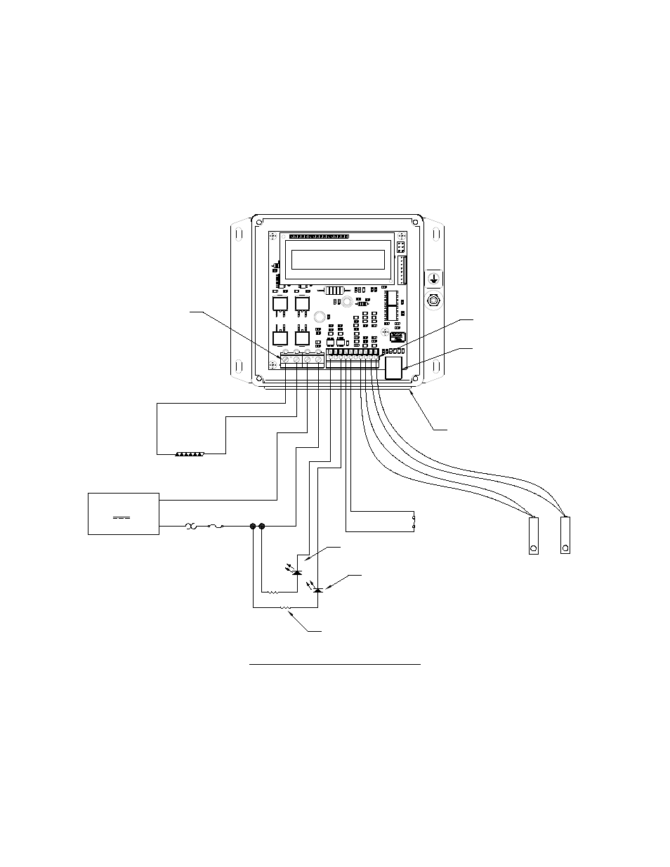
Connect other applicable devices to the controller:
a) Connect optional external alarm LED indicators to JP2-10 (ALARM2) and/or JP2-8 (ALARM1), assuming ALARM1
will not be configured for PWM fan control.
b) Connect optional enable/disable switch between JP2-6 and JP2-7 (or other circuit ground location). The
controller will need to be software programmed to enable this feature (described in Section 4). Once
programmed, when the switch is closed (electrically shorted), the controller’s power output will be enabled. If
the switch is open, the output will be disabled. The switch could, for example, be a simple rocker switch or it
could be a thermostat. The current between JP2-6 and JP2-7 will be 2 mA when the switch is closed. Use a
switch with the appropriate contact ratings, such as gold plated contacts.
Connections, Other Applicable Devices
c) If you intend to use the controller to speed-control a fan rated for PWM control, connect the PWM speed-
control wire as shown below through the rubber face plate, and connect to JP2-8. Be sure to consult the fan
manufacturer for further details on the appropriate PWM frequency to use with the fan, minimum duty cycle
required for the fan blade to spin, etc.
JP7
JP2
1
2
3
4
10
9
8
7
6
5
4
3
2
1
(+)
(-)
TE DEVICE
DC
POWER SUPPLY
OPTIONAL FUSE
THERMOSTAT AND OTHER
PROTECTIVE DEVICES
(CUSTOMER SUPPLIED)
OPTIONAL
SECONDARY
SENSOR
JP2-4 (+) and
JP2-3 (-)
CONTROL
SENSOR
JP2-1 (+) and
JP2-2 (-)
12 V, 36 V, 20 A maximum
JP7
PIN 1
JP2
PIN 1
WIRES MUST PASS THROUGH
GASKET HOLES
NOTE: LID IS REMOVED TO SHOW
WIRE CONNECTIONS
USB COMMUNICATION PORT
to JP7-1
to JP7-2
to JP7-3
to JP7-4
(+)
(-)
LED ALARM 2 INDICATOR
LED ALARM 1 INDICATOR
CURRENT LIMITING RESISTORS
to JP2-6
to JP2-7
OPTIONAL ENABLE/DISABLE
SWITCH (CUSTOMER
SUPPLIED)
to JP2-10
to JP2-8
24