Boring – Smithy Midas 1220 LTD User Manual
Page 66
Boring
Boring is internal turning, or turning from within. The diameter of the opening to be bored
is often much smaller than its depth. Boring tools must therefore have relatively small
diameters and still support a cutting edge projected at considerable distance from the
toolpost or compound rest.
Boring tools consist of an extremely stiff, strong bar with a formed cutting end or a way
to hold an HSS cutter or carbide insert. There are many sizes and types of boring bars.
Choose the one that will give the stiffest possible bar at every depth and diameter and
the greatest choice of cutters and cutter angles (ask a Smithy technician about the Smithy
boring head combo package, Item# K99-125).
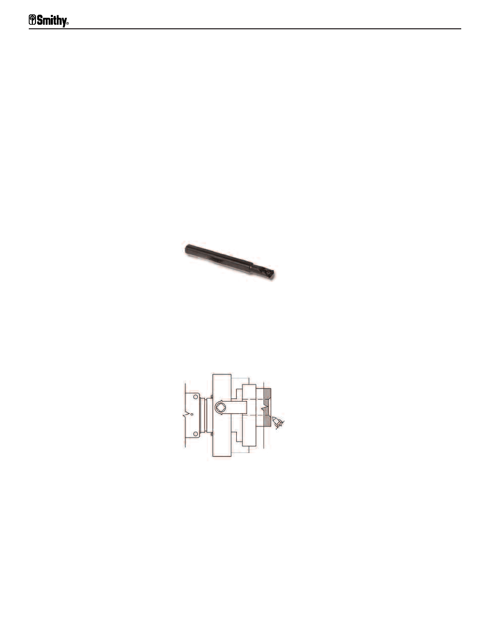
It is also wise to select tools with smooth-ended bars without a projecting nut or
hardened edge that might mar the work (Figure 14.2). Most boring tools have only one
cutting edge. There are double-end cutters, however, and they offer advantages in
special instances. In grinding cutters, allow sufficient end rake to provide clearance from
the internal diameter.
Figure14.2 A tool with a smooth-ended bar won't mark the workpiece.
Except with cored castings, pipes, or tubing, begin by drilling a hole large enough to
admit the end of the boring bar. Because the holes in cored castings often deflect boring
bars from their true axis, you may want to chamfer or turn out a starting cut in the open-
ing of the hole to be bored with a turning tool before introducing the
boring tool.
Figure 14.3 Chamfer a starting cut in the opening of the hole.
With the boring toolholder set up (in the toolpost or toolpost T-slot, depending on the
type), select the largest-diameter boring bar whose cutter the bore will accept. Extend
the bar from the holder just enough to reach the full depth to be machined and still allow
tool clearance. Except when using the adjustable boring tool (usually for very-large-
diameter work), feed the bar into the hole, parallel to the holes axis. The cutting edge
engages the work along a line in the mounted plane of the lathe centers with the bar
positioned to give the cutter a top rake of approximately 14° from the radius at the
cutting point (Figure 14.4). This takes into consideration the ground angle (top rake) of
the cutter itself.
Midas 1220 LTD Operator’s Manual
14-2
For Assistance: Call Toll Free 1-800-476-4849