Skutch Electronics CK-2 User Manual
Page 4
Page 4 of 5
Red = Line #1 Ring
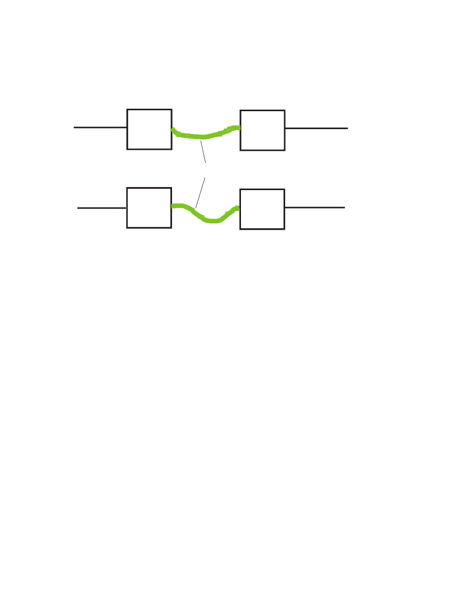
GREEN CORDS
are for Testing ONLY!
Green = Line #1 Tip They are removed before installing the CK-2.
Black = Line #2 Ring
Yellow = Line #2 Tip
1- When the jacks have been installed, without the modular cables attached as shown
above by the GREEN lines, all lines, on all phones should be dead. Check this before
continuing. If any of the phones get dial tone, the wiring is wrong. Fix this before
continuing.
2- Now attach the two modular cords (shown in GREEN), between the jacks, as shown
above. All lines should be working on all phones. If any lines are not working, the wiring
is wrong. Fix this before continuing!
3- Remove the two modular cords that are shown in GREEN.
4. Connect Jack
A
to any one of the five CK-2 jacks labeled "Phone 1 & 2".
5. Connect Jack
B
to "any one of the five CK-2 jacks labeled "Phone 3 & 4".
6. Connect Jack
C
to "To Phone Lines" "Lines 1 & 2"
7. Connect Jack
D
to "To Phone Lines" "Lines 3 & 4"
8- Connect the audio cable from your audio source to the "Audio In" jack on the CK-2. If
the audio source is a CD player, use the supplied audio cable with the CK-2. If your
source is a digital player, use the audio cable that came with it.
9- Connect Power Cube from CK-2 to power.
To Telephone Lines
To ALL Telephones
Lines
1&2
Lines
3&4
Lines
3&4
Lines
1&2
Modular Phone Cords
CO Side
Phone Side
A
B
C
D