Wiring and connections – RLE GD100 User Manual
Page 21
CTS-M17 Installation, Operation and Maintenance Manual
B84450-001-000 RG
May 12, 2005
20
4. Wiring and Connections
The M-17 has an isolated power supply. This means that the installer may use
different grounds (if any) on the power supply input side from those on the output
side. Signal return is not electrically connected. This increases the flexibility the
installer has in the powering and monitoring the system; however, on the other
hand one has to be careful that all grounds are accounted for.
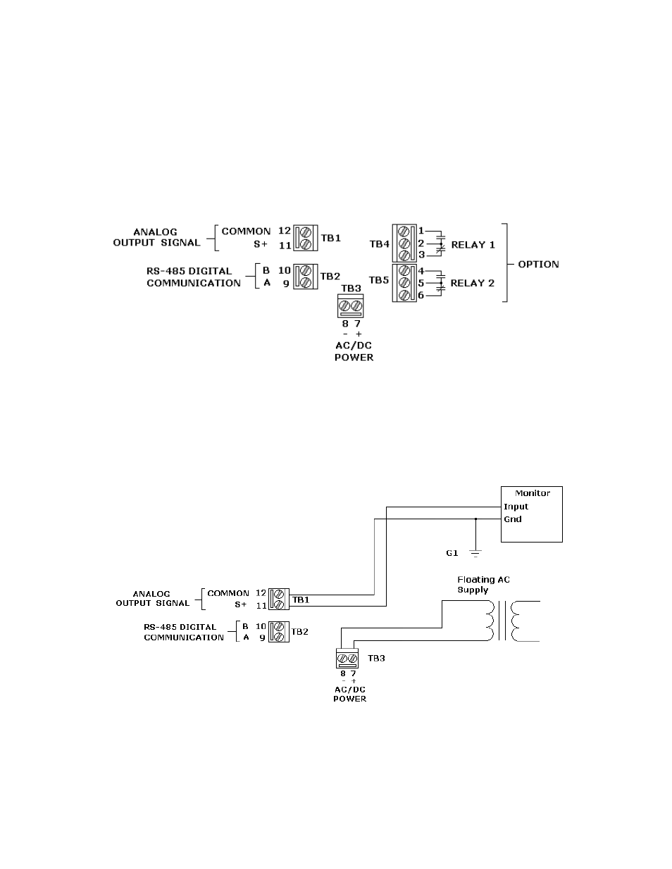
Figure 6 - Wiring Terminations (TB1, TB2, TB3, TB4 and TB5)
4.1 Power and Signaling
The following wiring diagrams list the various connection possibilities with respect
to the power supply and the 4 to 20 mA connection.
Figure 7 – 24VAC Floating Supply