2 fault code matrix, 3 hardware fault diagnostics – RLE GD100 User Manual
Page 20
CTS-M17 Installation, Operation and Maintenance Manual
B84450-001-000 RG
May 12, 2005
19
or while seeing the Model ID and Software Revision String (“QEL M-
17, V1.00…”). When the password request is seen, you can let go of
the key and enter the password in the normal fashion.
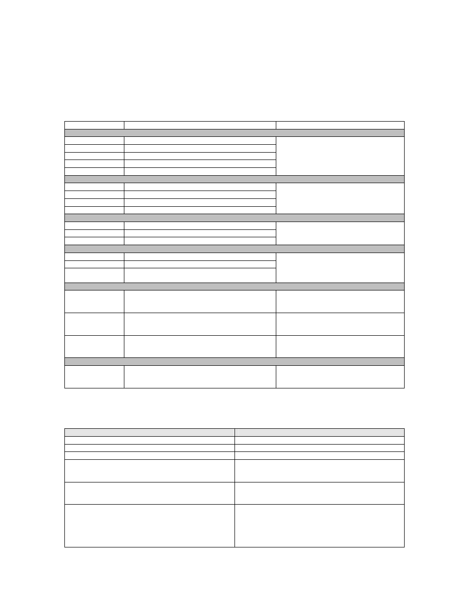
3.2 Fault Code Matrix
Fault Code
Description
Action
EEPROM
008
FLASH EEPROM write time-out.
009
Data EEPROM write time-out.
010
FLASH EEPROM verify error when writing.
011
Data EEPROM verify error when writing.
012
Last EEPROM write interrupted, incomplete.
Return unit to factory for repair if fault
persists.
Analog Output Signal
032
Driven output higher than monitored output.
033
Driven output lower than monitored output.
034
Voltage output load too large (or mode fault).
035
Voltage output load driving into unit.
Return unit to factory for repair if fault
persists.
System
024
Out of ms timers.
025
Out of second timers.
026
Message queue overflow.
Return unit to factory for repair if fault
persists.
Sensor
040
Sensor front-end or heater driver fault.
041
Pseudo ground level too low.
042
Pseudo ground level too high.
Check sensor, replace sensor and
calibrate.
Return unit to factory for repair if fault
persists.
Calibration
048
Concentration too far negative.
Calibrate.
Return unit to factory for repair if fault
persists.
049
Auto zero drifted too far low.
Calibrate.
Return unit to factory for repair if fault
persists.
050
Auto zero too far high, never came down from
initial value at start of auto-zero cycle.
Calibrate.
Return unit to factory for repair if fault
persists.
32-bit Mathematics
056
32-bit scale operation overflow.
Calibrate.
Return unit to factory for repair if fault
persists.
3.3 Hardware Fault Diagnostics
Fault Condition
Possible Solution
Screen Blank, no Signal
Check Wiring, check fuses.
Distorted MA Signal
Output jumper set to voltage.
Voltage signal pinned high
Output jumper set to mA
No mA Signal on AC floating power supply
Check for signal common line.
Check for signal operation by using on-board test
points
Bad RS-485 Communications for this unit.
Check wiring polarity for A & B lines
Check for correct line terminations.
Check for correct address.
Bad RS-485 Communications for a multi-drop
group.
Check wiring polarity for A & B lines
Check for correct line terminations.
It is possible for one failed device on a multi-drop
line to pull communication down for the whole line.
Check for correct addresses.