Electrical connection, Before commissioning – REMKO RVD xxx DC User Manual
Page 21
All electrical installation work
should be performed by spe-
cialist contractors. Isolate the
voltage supply when connect-
ing the electrical terminals.
!
CAUTION
Electrical connection
A protected mains supply cable
and control cable should be con-
nected to the outdoor component
RVD 351-1051DC and indoor unit
respectively.
NOTE
We recommend realising the
control lines with shielded
cable.
■
We recommend that custom-
ers install a main/repair switch
in the vicinity of the outdoor
component.
■
The terminal blocks for making
the connections are located at
the rear of the unit. When the
unit is installed, measurements
can be made from the front by
removing the cover.
■
If an optional condensation
pump is used in conjunction
with the unit, it may be neces-
sary to install an additional relay
with a higher contact rating
after the switch-off contact
on the pump to switch off the
compressor.
■
Control cables should be
screened if laid in areas exposed
to strong magnetic fields.
■
Details concerning the electrical
protection
of the system are given in the
section on technical data.
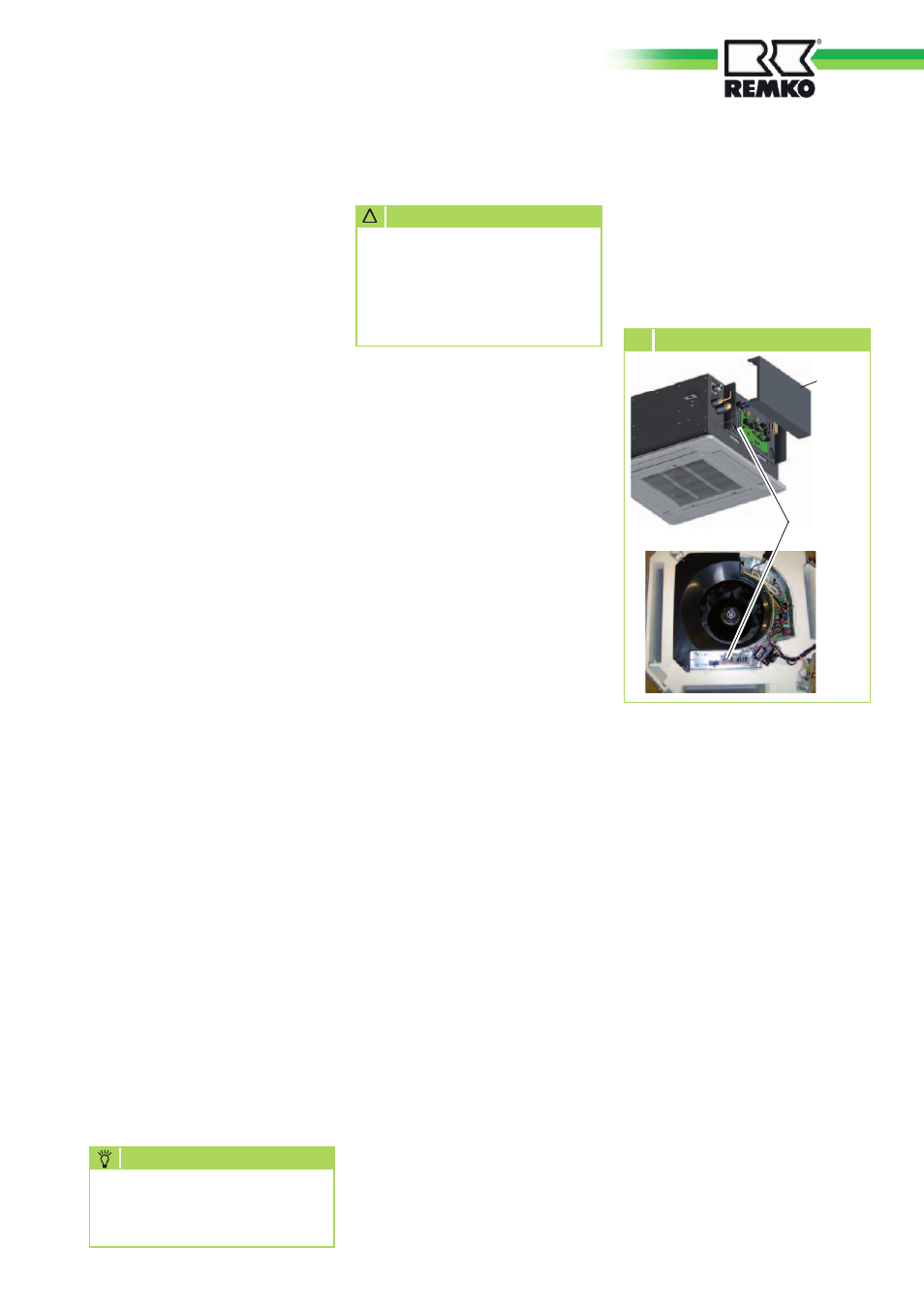
Connecting the indoor unit
Make the connection as follows:
1. Open the air intake grill.
2. Unfasten the cover on the
right side (RVD 351-521DC) or
below the panel (RVD 681-
1051DC (Fig. 13).
3. Connect the unit to the control
cable on the outdoor compo-
Connecting the outdoor unit
Proceed as follows to connect the
cable:
1. Remove the cover from the
unit.
2. Remove the side panel next to
the terminals.
3. Select the cable cross-section
according to the relevant stand-
ards.
4. Feed both cables through the
edge protection rings on the
fixed connection panel.
5. Terminate the cables as shown
on the electrical connection
diagram.
6. Support the cable in the strain
relief and re-assemble the unit.
After the tightness check has been
successfully completed,
connect the vacuum pump via the
pressure gauge station to the valve
connections on the outdoor unit
(see chapter "Tightness check")
and create a vacuum.
Perform the following checks prior
to commissioning the unit for the
first time and after any interven-
tions affecting the refrigerant
circuit. Record the results in the
commissioning report:
■
Check of all refrigerant
pipes and valves with
leak detection spray or soapy
water for leaks and for inad-
vertent mix up of suction and
injection pipe, with the unit at a
standstill.
■
Check of all refrigerant
pipes and insulation for dam-
age.
■
Check of all electrical
connections between
indoor unit and outdoor unit
for correct polarity.
■
Check that all fastenings,
mountings etc.
are firm and at the correct level.
Before
Commissioning
Cover
13
Connecting the indoor unit
Terminal
block
Control line
nent. See electrical connection
diagram.
4. Re-assemble the unit.
21