Remko mvt – REMKO MVT 600 DC User Manual
Page 6
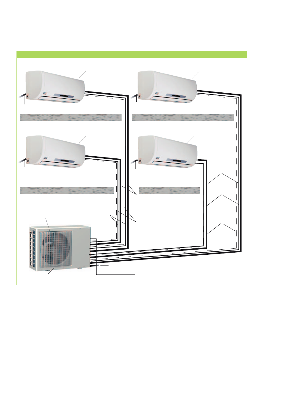
Outdoor unit
Indoor area A
Outdoor area
Stop valves
Liquefier fan
Indoor area B
Indoor area C
Indoor areaD
Indoor unit
Indoor unit
Indoor unit
Indoor unit
System design
The connection between indoor units (A, B, C, D) and outdoor units (connection circuit A, B, C, D) of the
outdoor unit is achieved with refrigerant pipes and a control line.
Injection pipe
Suction pipe
Injection pipe
Suction pipe
Condensation line
Condensation line
Condensation line
Condensation line
Mains cable
Control line
Control line
REMKO MVT
6
This manual is related to the following products: