Intended use – REMKO MVT 600 DC User Manual
Page 5
The equipment is shipped in sturdy
transport packaging. Immediately
check the equipment on delivery
and make a note of any damage or
missing parts on the delivery note.
Inform the forwarding agent and
contractual partner.
Warranty claims at a later date will
not be accepted.
Description of the
equipment
Transport and
packaging
The outdoor unit serves to output
the heat extracted by the indoor
unit from the room being cooled.
In heater operation, the heat taken
up by the outdoor unit can be
discharged by the indoor unit into
the room to be heated.
In both operating modes,
the output produced by the
compressor precisely matches
requirements, and thereby
regulates the nominal temperature
with minimal temperature
deviations. This "inverter-
technology" enables power saving
over a conventional split-system
and also reduces noise emissions
to a particularly low level.
The outdoor unit can be installed
outdoor or in indoor areas,
providing certain requirements are
met. The indoor unit is designed
for installation high up on interior
walls. It is operated via an infrared
remote control.
The outdoor unit is comprised of
a circuit containing a compressor,
a liquefier with fin vaporisers, three
electronic expansion valves and
a liquefier fan. The outdoor unit is
combinable with REMKO indoor
units of series MXW in accordance
with the cooling output (see
chapter "Combinations").
The outdoor unit refrigerant circuit
is controlled by the regulator in
the indoor unit. In order to enable
operation of the device at low
outdoor temperatures, a thermal
condenser pressure regulator
serves as winter controller to
regulate the speed of the liquefier
fan.
Floor consoles, wall consoles and
refrigerant pipes are available as
accessories.
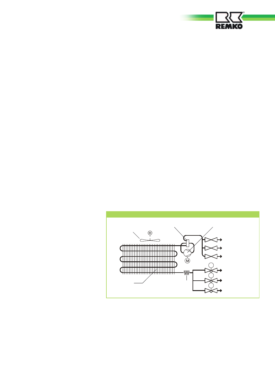
Schematic of outdoor refrigerant circuit
TCE
TCE
TCE
Liquefier fan
Reverse flow valve
Liquefier
Flow regulator
Capillary
tube
Injection pipe A
Injection pipe B
Injection pipe C
Connection valve
Suction pipe C
Connection valve
Suction pipe A
Connection valve
Suction pipe B
Compressor
Intended use
Depending on the model, the
equipment and the additional
fittings with which it is equipped
is only intended to be used as an
air-conditioner for the purpose of
cooling or heating the air in an
enclosed room.
Different or additional use shall not
be classed as intended use. The
manufacturer/supplier assumes no
liability for damages arising from an
unintended use of the equipment.
The user bears the sole risk in such
cases.
Using the equipment as intended
also includes working in accord-
ance with the operating manual
and installation instructions and
complying with the maintenance
requirements.
5