Unpacking the ri-1, Mounting the ri-1 repeater controller, Interface your receiver and transmitter – Pacific Research Solutions RI-1 User Manual
Page 8
Pacific Research Solutions
RI-1 and PE-1 User Manual
Page 2
SECTION 2
QUICK START
This section will cover the basics of installation and programming of your RI-1. You may also need to review section 4 or 5 for
more details on connecting your RI-1 to your repeater. Once you have covered these basics, we recommend that you
thoroughly review the complete manual in order to get the most out of your controller.
UNPACKING THE RI-1
Inspect the carton for the following contents and if any of the items that you have ordered are missing or damaged, notify your
dealer or the factory that shipped the unit to you.
1. RI-1 or PE-1 Repeater controller board with mating DB25S connector.
2. User manual on CD.
3. Mounting hardware.
MOUNTING THE RI-1 REPEATER CONTROLLER
1. An optional single controller chassis is available. Mounting holes are provided for the repeater controller board within the
enclosure.
2. The repeater builder can mount the RI-1 repeater controller in any enclosure of his choice. The enclosure that you select
should be strong enough to mechanically protect the contents. The enclosure should be made of metal with good shielding
properties. We do not recommend the use of a plastic enclosure in a RF environment. Mount the RI-1 unit with #4-40
standoffs on the mounting surface.
3. Avoid installing the RI-1 in the following places:
• Directly above a transmitter or power amplifier because of heat and RF considerations.
• Directly above any power supplies because of heat and 60 Hz coupling into the audio circuits.
INTERFACE YOUR RECEIVER and TRANSMITTER
The RI-1 repeater controller is very easy to interface with your repeater. Before you continue, you need to make the following
connections. All connections are covered with greater details in section 4 of this manual. If you are installing the PE-1, you
should go directly to section 5.
1. +12 Volts DC power source, J1 Pin 5. (Only on the RI-1, the PE-1 gets its power from the RI-300)
2. DC power ground, J1 Pin 21, J1 Pin 5.
3. Receiver audio, J1 Pin 2.
4. Receiver NSQ (Squelch), J1 Pin 6.
5. Receiver TSQ (CTCSS), J1 Pin 7, Optional.
6. Audio return and/or shield, J1 Pin 15.
7. Transmitter audio, J1 Pin 3
8. Transmitter keying circuit (PTT), J1 Pin 4.
See section 4 for more complete details on proper interfacing to your repeater transmitter and receiver.
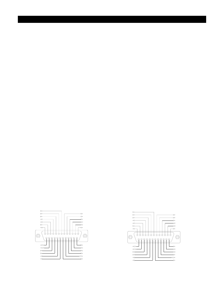
Audio Input (RX)
Audio-Ground
Digital-Ground
PTT (Open Drain)
Audio Output (TX)
+12V Supply
Radio Data Out
RI-1 Interface Connector
13
12
11
10
9
8
7
6
5
4
3
2
1
14
16
15
18
17
19
24
20 21 22 23
25
5Volts@25mA Out
Radio Data In
Radio Pwr Switch
Radio Pwr Detect
Sypply-Ground
User In 2
User In 1
SLE
SCK
SDA
RS-232 TXD
RS-232 RXD
RS-232 CTS
RS-232 RTS
User Out 1 (Open Drain)
User Out 2 (Open Drain)
TSQ (CTCSS)
NSQ (COS)
Audio Input (RX)
Audio-Ground
Digital-Ground
PTT (Open Drain)
Audio Output (TX)
Analog In
Radio Data Out
PE-1 Interface Connector
13
12
11
10
9
8
7
6
5
4
3
2
1
14
16
15
18
17
19
24
20 21 22 23
25
5Volts@25mA Out
Radio Data In
Radio Pwr Switch
Radio Pwr Detect
Sypply-Ground
User In 2
User In 1
SLE
SCK
SDA
RS-232 TXD
RS-232 RXD
RS-232 CTS
RS-232 RTS
User Out 1 (Open Drain)
User Out 2 (Open Drain)
TSQ (CTCSS)
NSQ (COS)