Communication settings, Gpc-xp controller technical guide, Before applying power – Orion System GPC-XP Controller User Manual
Page 7: Connect on board commlink, Stand alone operation, Network operation, Figure 3: gpc-xp controller address switch setting, On-board commlink setting, Ao ut 1 -2, Gpc-xp controller
GPC-XP Controller Technical Guide
Section 1: GPC-XP Wiring & Setup
7
Communication Settings
Before Applying Power
In order to have a trouble free start-up, it is important to follow a
few simple procedures. Before applying power for the fi rst time, it
is very important to correctly address the controller and run through
a few simple checks.
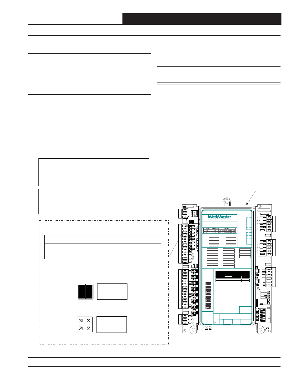
Communication Settings
Stand Alone Operation
The GPC-XP has an on-board CommLink that is used during Stand-
Alone Operation. When confi gured for Stand-Alone operation, a
computer running Prism 2 software can be connected directly to the
USB port located at the bottom of the GPC-XP for programming
and monitoring. In order to operate in Stand-Alone Mode, two
things need to be set. First, both CommLink Jumpers found on the
upper left hand side of the board need to be set to ON. See Figure
3
below
for details. Second, the Baud Rate determined by setting
ADDRESS Dipswitches 7 and 8 needs to be set to OFF/ON. See
Figure 4, page 8 for details.
NOTE: If using the Internal CommLink, you must set up
the USB drivers. See Appendix B, page 52.
Network Operation
The GPC-XP can be confi gured for connection to a networked system
that has an external CommLink. In this case, the on-board CommLink
would not be used. For this confi guration, two things need to be set.
First, both CommLink Jumpers found on the upper left found on the
upper left hand side of the board need to be set to OFF. See Figure
3
below
for details. Second, the Baud Rate determined by setting
ADDRESS Dipswitches 7 and 8 needs to be set to OFF/OFF if us-
ing a CommLink IV and to OFF/ON if using a CommLink 5. See
Figure 4, page 8 for details.
Figure 3: GPC-XP Controller Address Switch Setting
GPC-XP Controller
CO
M
F
R
O
M
G
ND
CUT
TO
IS
O
L
A
T
E
WATTMASTER CONTROLS
YS102432 REV 3
LOOP COMM
GND
+24V
+5V
OUTPUTS
ADDRESS
ADD
1
2
4
8
16
32
POWER
EBUS
STATUS2
STATUS1
OUTPUTS
ANALOG
SERIAL #
OUTPUTS
RELAY
SH
R+
T-
BIN8
BIN7
BIN6
BIN5
BIN4
BIN3
BIN2
BIN1
BINARY
INPUTS
INPUTS
ANALOG
0-5
v
0-10
v
4-
2
0
m
A
AO
UT
1
-2
C14
R109
TB8
U19
U17
TB7
TB6
TB4
TB3
TB2
TB1
SW1
R97
R74
R6
1
R59
R5
5
R51
R47
R4
3
R4
1
R3
8
R21
R16
R14
D13
D12
D10
D9
D8
D7
D6
C46
C36
C21
RLY1
RLY2
RLY3
RLY4
COMMON
MADE IN USA
RLY1
RLY2
RLY3
RLY4
COMMON
AOUT1
AOUT2
AOUT3
AOUT4
GND
GND
1002
1002
.1uF
.1uF
AO
UT
3
-4
GND
1002
1002
1002
1002
1002
1002
1002
1002
1002
1002
1002
1002
.1uF
.01uF
L
OOP
BAU
D
1
2
AI7
AI8
AI6
AI5
AI4
AI1
AI2
AI3
GND
GND
GND
GND
AI8
AI7
AI6
AI5
AI4
AI3
AI2
AI1
TH
E
R
M
VDC
300
300
300
300
300
300
300
300
COM
COM
COM
COM
D11
CONNEC
ON BOA
COMMLI
ON-BOARD COMMLINK SETTING
Jumper 2
ON
Jumper 1
OFF
ON
OFF
Use On-Board CommLink
Setting
Use External CommLink
CONNECT
ON BOARD
COMMLINK
Both Jumpers ON
CONNECT
ON BOARD
COMMLINK
Both Jumpers OFF
RELAY CONTACT
RATING IS 1 AMP
MAX @ 24 VAC
RS-485 COMMUNICATION LOOP. WIRE
“R” TO “R”, “T” TO “T” “SHLD” TO “SHLD”
RELAY 2
RELAY 6
RELAY 1
RELAY 5
RLY 1 =
VDC
OUTPUTS
AI1 =
+ 24 VDC
+ 5 VDC
GND
BI1 =
AO1 =
AI2 =
BI2 =
AO2 =
AI3 =
BI3 =
AO3 =
AI4 =
BI4 =
AO4 =
AI5 =
BI5 =
AI6 =
BI6 =
AI7 =
BI7 =
AI8 =
BI8 =
RLY 2 =
RLY 5 =
RLY 3 =
RLY 6 =
RLY 4 =
RLY 7 =
RLY 8 =
RELAY 3
RELAY 7
RELAY 4
RELAY 8
COMMON
COMMON
USB
PORT
E-BUS
PORT
NOTES:
1.) ANALOG INPUT JUMPER SETTINGS MUST BE
SET FOR YOUR SPECIFIC INPUT DEVICE
REQUIREMENT.
2.) IT IS RECOMMENDED THAT YOU WRITE THE
DESCRIPTION OF THE INPUT, AND/OR
OUTPUTS YOU ARE CONNECTING TO THE
CONTROLLER IN THE BOXES PROVIDED ABOVE
USING A PERMANENT MARKER (SHARPIE) FOR
FUTURE REFERENCE.
®
24 VAC POWER ONLY
WARNING! POLARITY MUST BE OBSERVED
OR THE CONTROLLER WILL BE DAMAGED
www.wattmaster.com
AI1
AI2
AI3
AI4
AI5
AI6
AI7
AI8
THE
R
M
4-20
mA
0-
10
V
0-
5V
ANALOG
INPUT
JUMPERS
LED BLINK CODES
LED NAME
STATUS1
STATUS2
NORMAL OPERATION
0
1
SCHEDULE OVERRIDE
0
2
OE338-23-GPC-XP
GPC-XP CONTROLLER
WattMaster Label
#LB102095
Rev.: 1C
+2
4
VA
C
GND
Note:
The Power To The Controller Must Be Removed And
Reconnected After Changing The Address Switch
Settings In Order For Any Changes To Take Effect.
Caution:
Disconnect All Communication Loop Wiring From The
Controller Before Removing Power From The Controller.
Reconnect Power And Then Reconnect Communication
Loop Wiring.