Section 3: venting, Section 3-1, Converting to rear vent – Montigo H42DF User Manual
Page 8: Installation
H*42DF Indoor Gas Fireplace
Page 8
XG0148 - 150204.1
Installation
Section 3: Venting
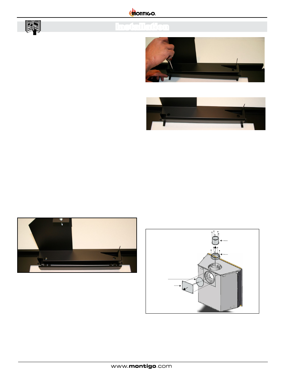
Figure 9. Flue cover and collar removal, Top Vented fireplace.
Section 3-1:
Converting to Rear Vent
Use the following instructions to convert an H*42DF* for Rear Vent use:
1. Remove the Rear flue cover and gasket (5" and 8") on the flue
outlet, as shown in Figure 9.
2. Next, Remove the Top flue collar's (5" and 8") on the flue outlet,
as shown in Figure 9.
3. Install the (removed) Rear flue cover and gasket material, to the
Top vent outlet. Fasten the cover with included hardware, as
illustrated Figure 9a.
4. Install the (5" and 8") collars to the rear vent outlet using the
included hardware, as illustrated Figure 9a.
5” Inner Flue Collar
8” Outer Flue Collar
Flue Gasket
Flue Cover Plate
Montigo supplies a variety of direct venting and termination options.
The direct vent termination location MUST be selected such that
it is the highest point in the venting assembly. It should also be
selected such that it provides the shortest vent run possible. Should
it be impossible to ensure that the termination is the highest point
or to meet the venting guidelines laid out below please contact your
Montigo dealer to discuss power venting options.
NOTES FOR PLANNING VENTING:
Venting originates from the unit through the top or through
the rear
Venting can terminate through the roof or through an
exterior wall.
Refer to Appendix A -Termination Locations to ensure the
planned termination location is acceptable.
Once the termination location has been established, refer
to the appropriate section for installation details.
All fireplaces shipped from the factory are Top vent.
Silicone application is NOT required when joining Montigo
vent pipes and components.
See Section 3-1 for converting the unit from top vent to rear vent.
NOTE: Air Baffle is shipped open. If you are top venting the air baffle
should be closed following these steps:
Figure 6. Air baffle in open position.
Figure 7.
Push the air baffle inward as far as possible and screw the air
baffle closed.
Figure 8. Air baffle in closed position
Note: Images are shown without screens for clarity purposes. However,
your fireplace should not be operated without proper installation of
screens.