Installation – Montigo H34DF User Manual
Page 15
H*34DF Indoor Gas Fireplace
Page 15
XG0146 - 150204
Installation
18
26
A
C
B
Acceptable
Vent run within
non-shaded area
Horizontal Run (in.)
Ve
rt
ical Height (in.)
Unacceptable Vent run
within shaded area
48
50
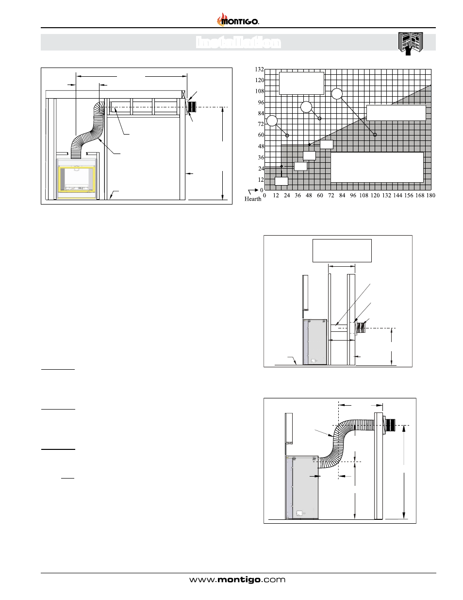
Figure 16. H*34DF* Rear Vent Venting Graph for wall mounted terminations,
See Figures 16a or 16b.
Figure 16b. Rear Vented, wall mounted Multi-elbow termination installation.
Multi-elbow venting Installation for H*34DF* must have a minimum vertical rise
of 50".The vent run must comply with the Venting Graph for Rear vent, wall
mounted terminations, Figure 16.
The Venting Graph
Measure the vertical height from the fireplace hearth to the centre of the
termination and the horizontal run from the fireplace flue collar to the wall
flange of the termination. Plot on the Venting Graph Figure 16 with an 'X'.
If the 'X' falls on or above the top boundary of the shaded area, the
installation is acceptable.
Example A: (Acceptable Installation)
If the vertical dimension from the hearth is 60" and the horizontal run to
the wall flange of the vent termination is 24", this would be an acceptable
installation.
Example B: (Acceptable Installation)
If the vertical dimension from the hearth is 78" and the horizontal run to
the wall flange of the vent termination is 60", this would be an acceptable
installation.
Example C: (Unacceptable Installation)
If the vertical dimension from the floor of the fireplace is 60" and the
horizontal run to the wall flange of the vent termination is 120", this
would NOT be an acceptable installation.
Figure 16a. Straight run, Rear Vented, wall mounted termination for H*34DF*,
Figure 16.
If your installation does not fall within the
venting graph parameters, (non-Shaded
area) please contact a local Montigo
dealer for Power Venting options.
30” Max.
50” Min.
18”
Max.
Flex or Rigid
Section
24”
Min.
26”
Acceptable Vent
run within non-
shaded area.
Acceptable Vent run
within non-shaded area.
26”
MXT Extension
RHS100 Heat
Shield
Termination
Hearth
Exterior
Wall
NOTE:
18” MAX. horizontal
run with no vertical lift.
18” MAX.
Figure 15b. Top Vented, wall mounted Multi-elbow installation. See
Venting Graph for Top vent, wall mounted terminations, Figure 14 or 15.
Notes Wall Mounted Terminations: TOP VENT
All measurements for vertical or horizontal runs are measured
from centre of the vent pipe.
Venting runs must fall within the limits set by the venting graph,
see Figure 16.
The fireplace must be converted to Rear Vent configuration prior
to running vent, see Figure 9 and 9a.
Solid Section
Flex Section
Hearth
30”min
15’ Max.
Heat
Shield
Termination
Exterior
Wall
8' MIN
at MAX
horizontal