MK Products CobraMig 260 PS/Feeder User Manual
Page 23
CobraMig 260 Owner's Manual - Page 17
Testing the Feeder
Relay K2 Operation
When the torch trigger is pressed, 24VAC is sent to the coil of relay K2. When
K2 is energized, 115VAC is sent to the slave motor, spool brake, and the
115VAC contactor. Relay K2 is also responsible for sending 24VAC to the
speed control circuit and shorting the torch motor leads together when the
trigger is released for the dynamic braking system. K2 also provides the
closing contactor signal.
Testing the 115 VAC Circuits
The 115 VAC circuit is protected by fuse F3. If F3 continually blows, remove
J4 (Brake Solenoid), J7 (slave motor) and J5-3,4 (115 VAC Contactor) from
the P.C. Board. Replace fuse, and retrigger system. If fuse does not blow;
isolate the problem by plugging in J4, J7, and J5-3,4 one at a time until
the fuse blows.
Testing the Torch
Motor Check
Remove the amphenol connector from the cabinet.
Using the torch amphenol, check the resistance across pins “A” and
“B”(motor leads). The resistance across the motor should be between 5-10
ohms.
If an open circuit or short exist, check the motor leads and motor
independently.
Testing the Potentiometer - “W” Clocked
Using the torch amphenol, check the resistance across pin “D” (wiper) and
pin “C”. The resistance should vary from 0 - 5K ohms.
Check the resistance across pin “D” (wiper) and pin “G”. The resistance
should vary from 5K - 0 ohms.
Testing the Micro Switch
Using the torch amphenol, check for continuity across pins “E” and “F” when
the trigger is pressed.
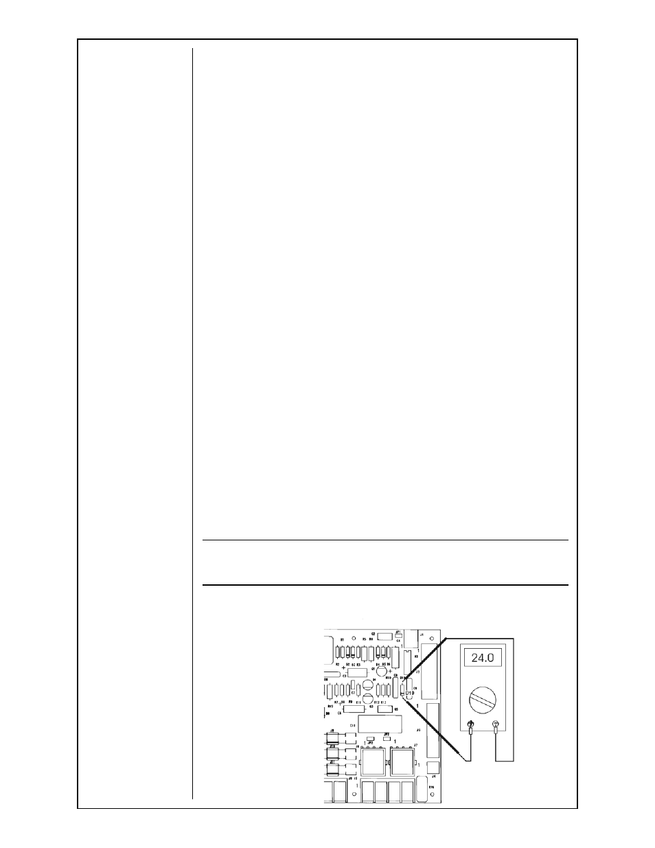
Testing the Speed Control
NOTE:
The torch should be tested fi rst and the torch panel amphenol must be
connected to the Cobramatic I to perform this test.
Place a voltmeter across diode D10 and press torch trigger. A reading of
0 - 24VDC should be observed, as the potentiometer varied.
Cobramtatic Main Board