B7874 – Microsonic zws-7/CD/QS User Manual
Page 2
Technical data
Blind zone
Operating range
Maximum range
Angle of beam spread
20 mm
70 mm
20 mm
150 mm
100 mm
See detection zone
250 mm
See detection zone
Transducer frequency
Resolution, sampling rate
Reproducibility
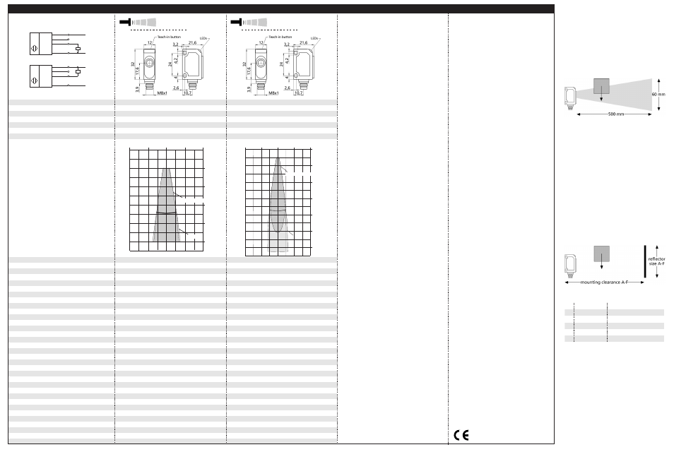
Detection zones
for different objects:
The dark grey areas are determined
with a thin round bar (10 mm dia.)
and indicate the typical operating range
of a sensor. In order to obtain the light grey
areas, a plate (100 x 100 mm) is introduced
into the beam spread from the side.
In doing so, the optimum angle between
plate and sensor is always employed.
This therefore indicates the maximum
detection zone of the sensor.
It is not possible to evaluate ultrasonic
reflections outside this area.
380 kHz
0,20 mm
380 kHz
0,20 mm
± 0,15 %
± 0,15 %
Accuracy
Operating voltage U
B
Voltage ripple
No-load current consumption
Temperature drift 0,17 % / °C
20 - 30 V DC, reverse polarity protection
Temperature drift 0,17 % / °C
20 - 30 V DC, reverse polarity protection
±10 %
< 30 mA
±10 %
< 30 mA
Housing
Class of protection to EN 60 529
ABS
ultrasonic transducer: polyurethane foam,
ABS
ultrasonic transducer: polyurethane foam,
epoxy resin with glass content
IP 67
epoxy resin with glass content
IP 67
Type of connection
Controls
Indicators
4-pin M8 initiator plug
Yes, Teach-in push-button
4-pin M8 initiator plug
Yes, Teach-in push-button
LED green (operation)
LED yellow (state of output)
LED green (operation)
LED yellow (state of output)
Programmable
Synchronisation
Pulse width synchronization signal t
p
Repetition rate synchronization signal t
p
No
Yes, external
No
Yes, external
> 150 µs
2 ms < t
p
< 1 s
> 150 µs
5 ms < t
p
< 1 s
Operating temperature
Storage temperature
Weight
Switching hysteresis
-25°C to +70°C
-40°C to +85°C
-25°C to +70°C
-40°C to +85°C
10 g
2 mm
10 g
2 mm
Switching frequency
Response time
Switch-off delay time
Time delay before availability
250 Hz
< 3 ms
100 Hz
< 7 ms
< 3 ms
< 300 ms
< 7 ms
< 300 ms
Norm conformity
Order no.
Switched output
EN 60947-5-2
EN 60947-5-2
zws-7/CD/QS
pnp, U
B
-2 V, I
max
= 200 mA
zws-15/CD/5ms.a
pnp, U
B
-2 V, I
max
= 200 mA
Order no.
Switched output
switchable NOC/NCC, short-circuit-proof
switchable NOC/NCC, short-circuit-proof
zws-7/CE/QS
npn, -U
B
+2 V, I
max
= 200 mA
zws-15/CE/5ms.a
npn, -U
B
+2 V, I
max
= 200 mA
switchable NOC/NCC, short-circuit-proof
switchable NOC/NCC, short-circuit-proof
1
2
4
3
+U
B
-U
B
Sync
U
1
2
4
3
+U
B
-U
B
Sync
U
1 pnp switched output
1 npn switched output
zws-7...
zws-15...
2 cm
0 cm
2 cm
0 cm
2 cm
4 cm
6 cm
7 cm
8 cm
10 cm
Plate
Round bar ø 10 mm
4 cm
4 cm
8 cm
4 cm
0 cm
4 cm
8 cm
0 cm
4 cm
8 cm
12 cm
16 cm
20 cm
24 cm
Round bar ø 10 mm
Plate
microsonic GmbH • Hauert 16 • D-44227 Dortmund • Tel: +49 2 31 / 97 51 51-0 • Fax: +49 2 31 / 97 51 51-51 • E-Mail: [email protected] • www.microsonic.de
The content of this document is subject to technical changes. Specifications in this document are presented in a descriptive way only. They do not warrant any product features.
*B7874*
MV-DO-085271-408188
responding to echoes from exis-
ting measurements. To avoid this,
there has to be an unobstructed
space extending to a depth of 500
mm in front of the sensor. Only
the objects to be detected are to
be within the sensor's 20-100 mm
operating area.
Fig. 5: Unobstructed space in front of the
sensor
With the zws-7, it is vital that the
objects to be detected enter the
sound fields from the sides..
If the unobstructed 500 mm space
cannot be provided or should the
sensor be used in the «Two-way
reflective barrier» mode, then a
plane reflector at a specific distan-
ce to the sensor must be fitted.
The size of the reflector and its
working clearance from the sensor
can be taken from the table in
Fig.7.
Fig. 6: Sensor/reflector working clearance
Fig. 7: Working clearance and reflector sizes
In the »Two-way reflective barrier«
operating mode, the object has to
be within the range of 0-85 % of
the set distance.
The zws-7 sensor has no tempera-
ture compensation.
If the push-button is not pressed
for 2 minutes during the teach-in
setting, the settings made hitherto
are deleted.
The sensor can be reset to its fac-
tory setting.
A
B
C
D
E
F
366 mm
60 mm x 60 mm
194 mm
137 mm
60 mm x 60 mm
50 mm x 50 mm
108 mm
91 mm
40 mm x 40 mm
40 mm x 40 mm
79 mm
30 mm x 30 mm
89/336/EEC