Microsonic mic-25/IU/M User Manual
Set the mic-sensor using the teach-in procedure, Instruction manual, Mic ultrasonic sensors with one analogue output
89/336/EEC
Product description
The mic-sensor with one analogue output
measures the distance to an object within
the detection zone contactless. A signal
proportional to distance is created ac-
cording to the adjusted window
margings of the analogue characteristic
curve.
The sensor automatically detects the load
put to the analogue output and switches
to current output or voltage output
respectively.
Choosing between rising and falling out-
put characteristic is possible.
The sensors are adjustable using Teach-in
processes via the Com-channel (Pin 5).
Using the LinkControl adapter (optional
accessory) all Teach-in and additional sen-
sor parameter settings may be made by a
Windows-Software.
Important instructions for assembly and
application
All employee and plant safety-relevant
measures must be taken prior to assembly,
start-up, or maintenance work (see operation
manual for the entire plant and the operator
instruction of the plant).
The sensors are not considered as safety
equipment and may not be used to ensure
human or machine safety!
The mic-sensors indicate a blind zone, in
which the distance cannot be measured. The
operating range indicates the distance of the
sensor that can be applied with normal re-
flectors with sufficient function reserve.
When using good reflectors, such as a calm
water surface, the sensor can also be used up
to its maximum range. Objects that strongly
absorb (e.g. plastic foam) or diffusely reflect
sound (e.g. pebble stones) can also reduce
the defined operating range.
Assembly instructions
Assemble the sensor at the installation lo-
cation.
Plug in the connector cable to the M 12
connector.
Abb. 1: Pin assignment with view onto sensor
plug and colour coding of the
microsonic connection cable
Synchronisation
If the assembly distances shown in Fig. 2 for
two or more sensors are exceeded the inte-
grated synchronisation should be used. Con-
nect Sync/Com-channels (pin 5 at the units re-
ceptable) of all sensors (10 maximum).
1
3
colour
+U
B
-U
B
brown
blue
4
2
5
-
I/U
black
white
Com.
grey
1
5
2
3
4
Abb. 2: Assembly distances
Start-up
mic-sensors are delivered factory made with
the following settings:
Rising analogue characteristic
Window margins for the analogue out-
put set to blind zone and operating
range
Maximum detection range set to maxi-
mum range
Set the parameters of the sensor using the
Teach-in procedure to adjust the analogue
chacteristc curve.
Operation
mic-sensors work maintenance free. Small
amounts of dirt on the surface do not influ-
≤ 0.35 m
≤ 0.40 m
≤ 2.50 m
≤ 2.50 m
≤ 1.10 m
≤ 2.00 m
≤ 2.50 m
≤18.00 m
≤ 4.00 m
≤30.00 m
A
B
ence function. Thick layers of dirt and ca-
ked-on dirt affect sensor function and the-
refore must be removed.
Note
mic-sensors have internal temperature
compensation. Because the sensors heat
up on their own, the temperature com-
pensation reaches its optimum working
point after approx. 30 minutes of opera-
tion.
The load put to the analogue output is
detected automatically when turning
supply voltage on.
If no signal is detected for 20 seconds
during teach-in procedure the made
changes are stored and the sensor re-
turns to normal mode operation.
You can reset the factory settings at any
time, see »Reset to factory setting«.
Teach-in switched output
Instruction manual
mic Ultrasonic Sensors with
one analogue output
mic-25/IU/M
mic-35/IU/M
mic-130/IU/M
mic-340/IU/M
mic-600/IU/M
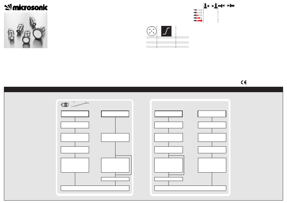
Additional settings
Set the mic-sensor using the Teach-in procedure
Set window margins
Place object
at position
Connect Com for about
3 s with + U
B
Place object
at position
Connect Com for about
1 s with + U
B
Set rising / falling output
characteristic curve
Connect Com for about
13 s with + U
B
To change output
function
connect Com for about
10 s with + U
B
Change Teach-in / Syn-
chronisation
Turn supply voltage OFF
Reset to factory setting
Turn supply voltage OFF
While Com is connected
to - U
B
turn supply
voltage ON
Keep Com connected to
- U
B
for about 3 s
To change operation
mode (Teach-in and Syn-
chronisation)
connect Com
for about 1 s to - U
B
While Com is connected
to - U
B
turn supply
voltage ON
Keep Com connected to
- U
B
for about 13 s
Disconnect
Com from - U
B
before swit-
ching-off
supply voltage
Normal operation mode
Wait for 10 s
Wait for 20 s
Normal operation mode
Tech-in analogue output
Further Settings
◀
◀