Microsonic nano-15/CD User Manual
Ultrasonic sensors
Operating Instructions
Ultrasonic proximity switch with
one switched output
nano-15/CD
nano-15/CE
nano-24/CD
nano-24/CE
Product description
The nano sensor offers a non-contact
measurement of the distance to an
object which must be positioned
within the sensor’s detection zone.
The switched output is set condi-
tional upon the adjusted detect dis-
tance.
Via the Teach-in procedure, the de-
tect distance and operating mode
can be adjusted. One 2-colour LED
indicates operation and the state of
the switched output.
Safety notes
Read the operating instructions
prior to start-up.
Connection, installation and
adjustment works should be car-
ried out by expert personnel only.
No safety Component in accor-
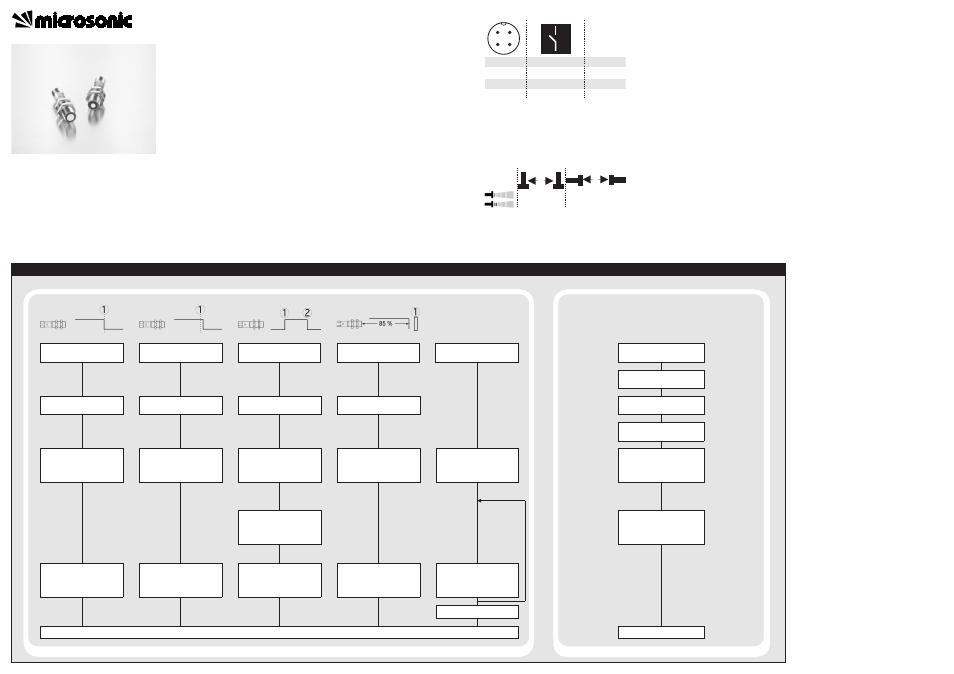
Sensor adjustment with Teach-in procedure
Set detect point -
method A
Place object at
position .
Connect Teach-in for
about 3 s to +U
B
, until
LED flashes yellow.
LED: flashes
green/yellow
Set detect point+8 % -
method B
Place object at
position .
Connect Teach-in for
about 3 s to +U
B
, until
LED flashes yellow.
LED: flashes
green/yellow
Set window mode
Set two way reflective
barrier
Set NOC/NCC
Place object at
position .
Install reflector at
position .
Connect Teach-in for
about 3 s to +U
B
, until
LED flashes yellow.
LED: flashes
green/yellow
Connect Teach-in for
about 3 s to +U
B
, until
LED flashes yellow.
LED: flashes
green/yellow
Connect Teach-in for
about 13 s to +U
B
, until
LED flashes green/yellow
alternately.
LED flashes: green, green/
yellow:
NOC
green:
NCC
Reset to factory setting
Switch off operating
voltage.
Connect Teach-in to +U
B.
Switch on
operating voltage.
Keep Teach-in connected
to +U
B
for about 13 s,
until LED flashes
green/yellow alternately.
Connect Teach-in for
about 1 s to +U
B.
Normal operating mode
Connect Teach-in for
about 3 s to +U
B
, until
LED flashes green/yellow.
Place object at
position .
LED: flashes
green/yellow
Connect Teach-in for
about 1 s to +U
B.
Connect Teach-in for
about 10 s to +U
B
until
both LEDs stop flashing.
To change output
characteristic connect
Teach-in for about
1 s to +U
B
.
Wait for 10 s.
Disconnect Teach-in from
+U
B
within 5 s before
switching off
supply voltage.
Normal operating mode
dance with the EU Machine Direc-
tive.
Use for intended purpose only
nano ultrasonic sensors are used for
non-contact detection of objects.
Installation
Mount the sensor at the installa-
tion site.
Connect a connection cable to the
M12 device plug.
The assembly distances shown in fig.
2 for two or more sensors should not
be fallen below in order to avoid mu-
tual interference.
Start-up
Connect the power supply.
Carry out sensor adjustment in
accordance with the diagram.
Fig. 1: Pin assignment with view onto sensor
plug and colour coding of the
microsonic connection cables
Fig.2: Assembly
distances
1
3
colour
+U
B
-U
B
brown
blue
4
2
D/E
Teach-in
black
white
1
2
3
4
≥0.25 m
≥1.3 m
≥0.25 m
≥1.4 m
A
B
Factory setting
Detect point operation.
Switched output on NOC.
Detect distance at operating
range.
Operating modes
Three operating modes are available
for the switched output:
Operation with one detect point
The switched output is set when the
object falls below the set detect
point.
Window mode
The switched output is set when the
object is within the set window.
Two-way reflective barrier
The switched output is set when the
object is between sensor and fixed
reflector.
Maintenance
microsonic sensors are maintenance-
free. In case of excess caked-on dirt
we recommend cleaning the white
sensor surface.
Notes
Every time the power supply is
switched on, the sensor detects its
actual operating temperature and
transmits it to the internal tempe-
rature compensation. This results
in a slight correction of the ana-
logue output value after 45 se-
conds.
If the sensor was switched off for
at least 30 minutes and after po-
wer on the switched output is not
set for 30 minutes a new adjust-
ment of the internal temperature
compensation to the actual moun-
ting conditions takes place.
The sensors of the nano family
have a blind zone. Within this
zone a distance measurement is
not possible.
In the normal operating mode, an il-
luminated yellow LED signals that the
switched output is switched
through.
In the »Two-way reflective barrier«
operating mode, the object has to
be within the range of 0-85 % of
the set distance.
In the »Set detect point - method
A« Teach-in procedure the actual
distance to the object is taught to
the sensor as the detect point. If
the object moves towards the
sensor (e.g. with level control) then
the taught distance is the level at
which the sensor has to switch the
output.
If the object to be scanned moves
into the detection area from the
side, the »Set detect point+8 % -
method B« Teach-in procedure
should be used. In this way the
switching distance is set 8 % fur-
ther than the actual measured dis-
tance to the object. This ensures a
reliable switching distance even if
the height of the objects varies
slightly.
Ultrasonic Sensors
Set switched output
Further Settings