Microsonic pico+15/F User Manual
Ultrasonic sensors
Operating Instructions
Ultrasonic proximity switch with
one switched output
pico+15/F
pico+15/WK/F
pico+25/F
pico+25/WK/F
pico+35/F
pico+35/WK/F
pico+100/F
pico+100/WK/F
Product description
The pico+sensor offers a non-contact
measurement of the distance to an
object which must be positioned
within the sensor’s detection zone.
The switched output is set condi-
tional upon the adjusted detect dis-
tance.
Via the Teach-in procedure, the de-
tect distance and operating mode
can be adjusted. Two LEDs indicate
operation and the state of the swit-
ched output.
The pico+sensors are IO-Link-capable
in accordance with IO-Link specifica-
tion V1.0.
Safety instructions
Read the operating instructions
prior to start-up.
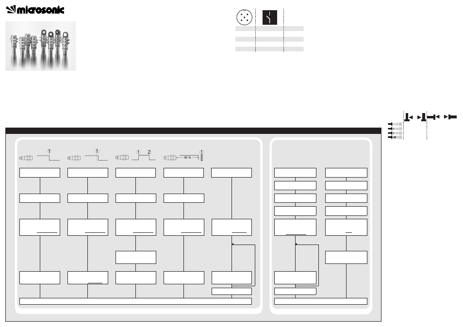
Sensor adjustment with Teach-in procedure
Set detect point
– method A
Place object at position
Connect Com for about
3 s to +U
B
, until both
LEDs flash simultaneously
Both LEDs:
flash alternately
Set detect point +8 %
– method B
Place object at position
Connect Com for about
3 s to +U
B
, until both
LEDs flash simultaneously
Both LEDs:
flash alternately
Set window mode
Set two way reflective
barrier
Set NOC/NCC
Place object at position
Install reflector at
position
Connect Com for about
3 s to +U
B
, until both
LEDs flash simultaneously
Both LEDs:
flash alternately
Connect Com for about
3 s to +U
B
, until both
LEDs flash simultaneously
Both LEDs:
flash alternately
Connect Com for about
13 s to +U
B
, until both
LEDs flash alternately
Green LED:
Yellow LED:
flashes
on: NOC
off: NCC
Switch-over
Teach-in / synchronisation
Switch off operating
voltage
Reset to factory setting
Switch off operating
voltage
Connect Com to -U
B
Switch on
operating voltage
Keep Com connected to
-U
B
for about 3 s, until
both LEDs flash
simultaneously
Green LED:
Yellow LED:
flash
on: Teach-in
off: Synchro-
nisation
Connect Com to -U
B
Switch on
operating voltage
Keep Com connected to
-U
B
for about 13 s, until
both LEDs stop flashing
Connect Com for about
1 s to +U
B
Normal operating mode
Connect Com for about
3 s to +U
B
, until both
LEDs flash alternately
Place object at position
Both LEDs:
flash mutually
Connect Com for about
1 s to +U
B
Connect Com for about
10 s to +U
B
To change output
characteristic connect
Com for about 1 s to +U
B
Wait for 10 s
To change operation
mode connect
Com for about 1 s to -U
B
Wait for 10 s
Normal operating mode
Disconnect Com from -U
B
before switching off
supply voltage
Connection, installation and ad-
justments may only be carried out
by qualified staff.
No safety component in
accordance with the EU Machine
Directive
Use for intended purpose only
pico+ultrasonic sensors are used for
non-contact detection of objects.
Installation
Mount the sensor at the place of
fitting.
Connect a connection cable to the
M12 device plug.
Fig. 1: Pin assignment with view onto sensor
plug and colour coding of the
microsonic connection cables
Start-up
Connect the power supply.
Carry out sensor adjustment in
accordance with the diagram.
1
3
colour
+U
B
-U
B
brown
blue
4
2
5
F
-
black
white
Com
grey
1
5
2
3
4
Factory setting
Detect point operation
Switched output on NOC
Detect distance at operating range
Multi-function input »Com« set to
»Teach-in«
Filter at F01
Filter strength at P01
Operating modes
Three operating modes are available
for the switched output:
Operation with one detect point
The switched output is set when the
object falls below the set detect
point.
Window mode
The switched output is set when the
object is within the set window.
Two-way reflective barrier
The switched output is set when the
object is between sensor and fixed
reflector.
Synchronisation
If under multiple sensor operation
the assembly distance falls below the
values shown in Fig. 2, the internal
synchronisation should be used. For
this purpose set the switched out-
puts of all sensors in accordance with
the diagram »Sensor adjustment
with the Teach-in procedure«. Then
change the multi-function output
»Com« to »synchronisation« (see
»Further settings«). Finally intercon-
nect each pin 5 of the sensors to be
synchronised.
Fig. 2: Assembly distances
Maintenance
microsonic sensors are maintenance-
free. In case of excess caked-on dirt
we recommend cleaning the white
sensor surface
Notes
The sensors of the pico+ family
have a blind zone, within which a
distance measurement is not pos-
sible.
The pico+ sensors are equipped
with an internal temperature com-
pensation. Due to the sensors self
heating, the temperature compen-
sation reaches its optimum work-
ing-point after approx. 20 minutes
of operation.
In the normal operating mode, an il-
luminated yellow LED signals that the
switched output is switched
through.
The pico+sensors have a push-pull
switched output.
In the »Two-way reflective barrier«
operating mode, the object has to
be within the range of 0-85 % of
the set distance.
≥0,25 m
≥1,30 m
≥0,35 m
≥0,40 m
≥2,50 m
≥2,50 m
≥0,70 m
≥4,00 m
A
B
Ultrasonic Sensors
Set switched output
Further Settings