Microsonic nano-15/CD User Manual
Page 2
Technical data
blind zone
operating range
maximum range
angle of beam spread
20 mm
150 mm
40 mm
240 mm
250 mm
See detection zone
350 mm
See detection zone
transducer frequency
resolution, sampling rate
reproducibility
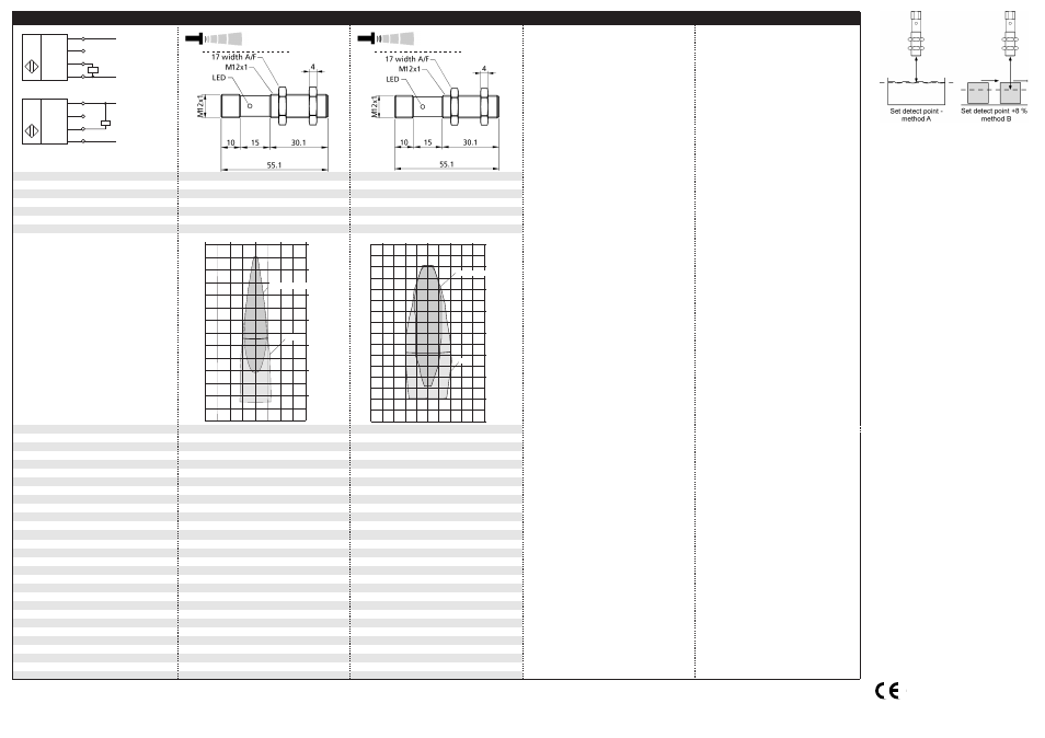
detection zones
for different objects:
The dark grey areas represent the zone
where it is easy to recognise the normal
reflector (round bar). This indicates the typical
operating range of the sensors. The light
grey areas represent the zone where a
very large reflector - for instance a
plate - can still be regognized. The
requirement here is for an optimum
alignment to the sensor. It is not
possible to evaluate ultrasonic
reflections outside this area.
380 kHz
69 µm
500 kHz
69 µm
± 0.15 %
± 0.15 %
accuracy
operating voltage U
B
voltage ripple
no-load current consumption
± 1 % (temperature drift internally compensated)
10 - 30 V DC, reverse polarity protection
± 1 % (temperature drift internally compensated)
10 - 30 V DC, reverse polarity protection
±10 %
< 25 mA
±10 %
< 35 mA
housing
max. tightening torque of nuts
brass sleeve, nickel-plated, plastic parts: PBT;
ultrasonic transducer: polyurethane foam,
brass sleeve, nickel-plated, plastic parts: PBT;
ultrasonic transducer: polyurethane foam,
epoxy resin with glass content
1 Nm
epoxy resin with glass content
1 Nm
class of protection per EN 60 529
norm conformity
type of connection
controls
IP 67
EN 60947-5-2
IP 67
EN 60947-5-2
4-pin M12 circular plug
Teach-in via pin 2
4-pin M12 circular plug
Teach-in via pin 2
indicators
programmable
operating temperature
storage temperature
LED yellow/green
Teach-in
LED yellow/green
Teach-in
-25°C to +70°C
-40°C to +85°C
-25°C to +70°C
-40°C to +85°C
weight
switching hysteresis
switching frequency
response time
15 g
2 mm
15 g
3 mm
25 Hz
24 ms
20 Hz
30 ms
time delay before availability
order no.
switched output
< 300 ms
< 300 ms
nano-15/CD
pnp, U
B
-2V, Imax = 200 mA
nano-24/CD
pnp, U
B
-2V, Imax = 200 mA
order no.
switched output
switchable NOC/NCC, short-circuit-proof
switchable NOC/NCC, short-circuit-proof
nano-15/CE
npn, -U
B
+2V, Imax = 200 mA
nano-24/CE
npn, -U
B
+2V, Imax = 200 mA
switchable NOC/NCC, short-circuit-proof
switchable NOC/NCC, short-circuit-proof
+U
B
-U
B
D
1
2
4
3
1 pnp switched output
U
+U
B
-U
B
E
1
2
4
3
1 npn switched output
U
Teach-in
Teach-in
nano-15...
nano-24...
8 cm
4 cm
0 cm
4 cm
8 cm
0 cm
4 cm
8 cm
12 cm
16 cm
20 cm
24 cm
Round bar ø 10 mm
Plate
10 cm
5 cm
0 cm
5 cm
10 cm
0 cm
5 cm
10 cm
15 cm
20 cm
25 cm
30 cm
35 cm
Plate
Round bar ø 10 mm
microsonic GmbH | Hauert 16 | Germany | 44227 Dortmund | Tel: +49 2 31 / 97 51 51-0 | Fax: +49 2 31 / 97 51 51-51 | E-Mail: [email protected] | www.microsonic.de The content of this document is subject to technical changes. Specifications in this document are presented in a descriptive way only. They do not confirm any product features.
Fig. 4: Setting the detect point for different
directions of movement of the object
The sensor can be reset to its fac-
tory setting (see »Further set-
tings«).
*B10706*
MV-DO-131212-458857
2004/108/EC