Microsonic pico+15/F User Manual
Page 2
Technical data
blind zone
operating range
maximum range
angle of beam spread
20 mm
150 mm
30 mm
250 mm
250 mm
see detection zone
350 mm
see detection zone
transducer frequency
resolution
reproducibility
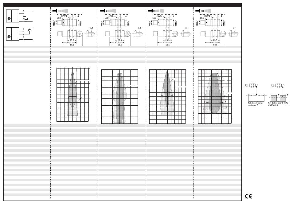
detection zones
for different objects:
The dark grey areas represent the zone
where it is easy to recognise the normal
reflector (round bar). This indicates the typical
operating range of the sensors. The light
grey areas represent the zone where a
very large reflector – for instance a
plate – can still be regognized. The
requirement here is for an optimum
alignment to the sensor. It is not
possible to evaluate ultrasonic
reflections outside this area.
380 kHz
0.069 mm
320 kHz
0.069 mm
± 0.15 %
± 0.15 %
accuracy
operating voltage U
B
voltage ripple
no-load current consumption
±1 % (temperature drift internally compensated)
10 - 30 V DC, reverse polarity protection
±1 % (temperature drift internally compensated)
10 - 30 V DC, reverse polarity protection
±10 %
< 40 mA
±10 %
< 40 mA
housing
max. tightening torque of nuts
brass sleeve, nickel-plated, plastic parts: PBT;
ultrasonic transducer: polyurethane foam,
brass sleeve, nickel-plated, plastic parts: PBT;
ultrasonic transducer: polyurethane foam,
epoxy resin with glass content
15 Nm
epoxy resin with glass content
15 Nm
class of protection per EN 60 529
type of connection
controls
indicators
IP 67
5-pin M12 circular plug
IP 67
5-pin M12 circular plug
Teach-in via pin 5 (Com)
LED green (operation)
Teach-in via pin 5 (Com)
LED green (operation)
programmable
synchronisation
operating temperature
LED yellow (state of output)
Teach-in, LinkControl
LED yellow (state of output)
Teach-in, LinkControl
internal synchronisation up to 10 sensors
-25°C to +70°C
internal synchronisation up to 10 sensors
-25°C to +70°C
storage temperature
switched output
switching hysteresis
1)
-40°C to +85°C
Push-Pull, I
max
= 100 mA
-40°C to +85°C
Push-Pull, I
max
= 100 mA
switchable NOC/NCC, short-circuit-proof
2 mm
switchable NOC/NCC, short-circuit-proof
3 mm
switching frequency
1)
response time
1)
time delay before availability
1)
norm conformity
25 Hz
32 ms
25 Hz
32 ms
< 300 ms
EN 60947-5-2
< 300 ms
EN 60947-5-2
order no. directly radiating
weight
pico+15/F
pico+25/F
30 g
30 g
order no. angular head
weight
1) Can be programmed with LinkControl
pico+15/WK/F
35 g
pico+25/WK/F
35 g
65 mm
350 mm
120 mm
1,000 mm
600 mm
see detection zone
1,300 mm
see detection zone
400 kHz
0.069 mm
200 kHz
0.069 mm
± 0.15 %
± 0.15 %
±1 % (temperature drift internally compensated)
10 - 30 V DC, reverse polarity protection
±1 % (temperature drift internally compensated))
10 - 30 V DC, reverse polarity protection
±10 %
< 40 mA
±10 %
< 40 mA
brass sleeve, nickel-plated, plastic parts: PBT;
ultrasonic transducer: polyurethane foam,
brass sleeve, nickel-plated, plastic parts: PBT;
ultrasonic transducer: polyurethane foam,
epoxy resin with glass content
15 Nm
epoxy resin with glass content
15 Nm
IP 67
5-pin M12 circular plug
IP 67
5-pin M12 circular plug
Teach-in via pin 5 (Com)
LED green (operation)
Teach-in via pin 5 (Com)
LED green (operation)
LED yellow (state of output)
Teach-in, LinkControl
LED yellow (state of output)
Teach-in, LinkControl
internal synchronisation up to 10 sensors
-25°C to +70°C
internal synchronisation up to 10 sensors
-25°C to +70°C
-40°C to +85°C
Push-Pull, I
max
= 100 mA
-40°C to +85°C
Push-Pull, I
max
= 100 mA
switchable NOC/NCC, short-circuit-proof
5 mm
switchable NOC/NCC, short-circuit-proof
20 mm
12 Hz
64 ms
10 Hz
80 ms
< 300 ms
EN 60947-5-2
< 300 ms
EN 60947-5-2
pico+35/F
pico+100/F
30 g
30 g
pico+35/WK/F
35 g
pico+100/WK/F
35 g
+U
B
-U
B
F
Com
1
2
4
5
3
Push-Pull output in pnp circuit
U
+U
B
-U
B
F
Com
1
2
4
5
3
Push-Pull output in npn circuit
U
pico+15...
pico+25...
8 cm
4 cm
0 cm
4 cm
8 cm
0 cm
4 cm
8 cm
12 cm
16 cm
20 cm
24 cm
Rohr ø 10 mm
ausgerichtete Platte
Plate
Rohr ø 10 mm
8 cm
0 cm
4 cm
8 cm
4 cm
8 cm
4 cm
0 cm
4 cm
8 cm
0 cm
4 cm
8 cm
12 cm
16 cm
20 cm
24 cm
Rohr ø 10 mm
ausgerichtete Platte
Round bar ø 10 mm
8 cm
0 cm
4 cm
8 cm
4 cm
0 cm
4 cm
8 cm
12 cm
16 cm
20 cm
24 cm
0 cm
5 cm
10 cm
15 cm
20 cm
25 cm
30 cm
35 cm
Plate
Round bar ø 10 mm
10 cm
5 cm
0 cm
5 cm
10 cm
pico+35...
pico+100...
0 cm
10 cm
20 cm
30 cm
40 cm
50 cm
60 cm
Plate
Round bar ø 27 mm
20 cm
10 cm
0 cm
10 cm
20 cm
35 cm
0 m
0,2m
0,8 m
1,0 m
1,3 m
0,4 m
0 m
0,4 m
0,6 m
0,4 m
1,0 m
1,4 m
0,2 m
0,2 m
Round bar ø 27 mm
Plate
■ In the »Set detect point – method
A« Teach-in procedure the actual
distance to the object is taught to
the sensor as the detect point. If
the object moves towards the
sensor (e.g. with level control) then
the taught distance is the level at
which the sensor has to switch the
output.
If the object to be scanned moves
into the detection area from the
side, the »Set detect point +8 % –
method B« Teach-in procedure
should be used. In this way the
switching distance is set 8 % fur-
ther than the actual measured dis-
tance to the object. This ensures a
reliable switching distance even if
the height of the objects varies
slightly.
Fig. 4: Setting the detect point for different
directions of movement of the object
If synchronization is activated the
Teach-in is disabled (see »Further
settings«).
The sensor can be reset to its fac-
tory setting (see »Further set-
tings«).
Using the LinkControl adapter (op-
tional accessory) and the LinkCon-
trol software for Windows, all
Teach-in and additional sensor pa-
rameter settings can be optionally
undertaken.
2004/108/EC