B8614 – Microsonic pico+15/I User Manual
Page 2
Technical data
blind zone
operating range
maximum range
angle of beam spread
20 mm
150 mm
30 mm
250 mm
250 mm
See detection zone
350 mm
See detection zone
transducer frequency
resolution
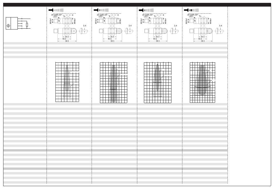
detection zones
for different objects:
The dark grey areas are determined with a
round bar and indicate the typical operating
range of a sensor. In order to obtain the light
grey areas, a plate (100 x 100 mm) is
introduced into the beam spread from the side.
In doing so, the optimum angle between
plate and sensor is always employed.
This therefore indicates the maximum
detection zone of the sensor.
It is not possible to evaluate ultrasonic
reflections outside this area.
380 kHz
0.069 mm
320 kHz
0.069 mm bis 0.10 mm, depending on the
analogue window
reproducibility
accuracy
no-load current consumption
operating voltage ripple
± 0.15 %
± 1 % (Temperature drift internal compensated)
± 0.15 %
± 1 % (Temperature drift internal compensated)
< 40 mA
±10 %
< 40 mA
±10 %
housing
max. tightening torque of nuts
brass sleeve, nickel-plated, plastic parts: PBT;
ultrasonic transducer: polyurethane foam,
brass sleeve, nickel-plated, plastic parts: PBT;
ultrasonic transducer: polyurethane foam,
epoxy resin with glass content
15 Nm
epoxy resin with glass content
15 Nm
class of protection to EN 60 529
type of connection
controls
indicators
IP 67
5-pin M12 initiator plug
IP 67
5-pin M12 initiator plug
Teach-in via pin 5 (Com)
LED green (operation)
Teach-in via pin 5 (Com)
LED green (operation)
programmable
synchronisation
operating temperature
LED yellow (state of analogue output)
Teach-in, LinkControl
LED yellow (state of analogue output)
Teach-in, LinkControl
internal synchronisation up to 10 sensors
-25°C to +70°C
internal synchronisation up to 10 sensors
-25°C to +70°C
storage temperature
response time
1)
time delay before availability
1)
norm conformity
-40°C to +85°C
32 ms
-40°C to +85°C
32 ms
< 300 ms
EN 60947-5-2
< 300 ms
EN 60947-5-2
analogue output 4-20 mA
operating voltage U
B
R
L
≤ 500 Ω, rising/falling characteristic
10 - 30 V DC for R
L
≤ 100 Ω,
R
L
≤ 500 Ω, rising/falling characteristic
10 - 30 V DC for R
L
≤ 100 Ω,
20 - 30 V DC for R
L
> 100 Ω,
terminal reverse polarity protected
20 - 30 V DC for R
L
> 100 Ω,
terminal reverse polarity protected
order no. directly radiating
weight
order no. angular head
weight
pico+15/I
30 g
pico+25/I
30 g
pico+15/WK/I
35 g
pico+25/WK/I
35 g
analogue output 0-10 V
operating voltage U
B
order no. directly radiating
R
L
≥ 100 kΩ, short circuit proof,
rising/falling characteristic
R
L
≥ 100 kΩ, short circuit proof,
rising/falling characteristic
15 - 30 V DC, terminal reverse polarity protected
pico+15/U
15 - 30 V DC, terminal reverse polarity protected
pico+25/U
weight
order no. angular head
weight
1) Can be programmed with LinkControl
30 g
pico+15/WK/U
30 g
pico+25/WK/U
35 g
35 g
65 mm
350 mm
120 mm
1,000 mm
600 mm
See detection zone
1,300 mm
See detection zone
400 kHz
0.069 mm bis 0.17 mm, depending on the
200 kHz
0.069 mm bis 0.38 mm, depending on the
analogue window
analogue window
± 0.15 %
± 1 % (Temperature drift internal compensated)
± 0.15 %
± 1 % (Temperature drift internal compensated)
< 40 mA
±10 %
< 40 mA
±10 %
brass sleeve, nickel-plated, plastic parts: PBT;
ultrasonic transducer: polyurethane foam,
brass sleeve, nickel-plated, plastic parts: PBT;
ultrasonic transducer: polyurethane foam,
epoxy resin with glass content
15 Nm
epoxy resin with glass content
15 Nm
IP 67
5-pin M12 initiator plug
IP 67
5-pin M12 initiator plug
Teach-in via pin 5 (Com)
LED green (operation)
Teach-in via pin 5 (Com)
LED green (operation)
LED yellow (state of analogue output)
Teach-in, LinkControl
LED yellow (state of analogue output)
Teach-in, LinkControl
internal synchronisation up to 10 sensors
-25°C to +70°C
internal synchronisation up to 10 sensors
-25°C to +70°C
-40°C to +85°C
64 ms
-40°C to +85°C
80 ms
< 300 ms
EN 60947-5-2
< 300 ms
EN 60947-5-2
R
L
≤ 500 Ω, rising/falling characteristic
10 - 30 V DC for R
L
≤ 100 Ω,
R
L
≤ 500 Ω, rising/falling characteristic
10 - 30 V DC for R
L
≤ 100 Ω,
20 - 30 V DC for R
L
> 100 Ω,
terminal reverse polarity protected
20 - 30 V DC for R
L
> 100 Ω,
terminal reverse polarity protected
pico+35/I
30 g
pico+100/I
30 g
pico+35/WK/I
35 g
pico+100/WK/I
35 g
R
L
≥ 100 kΩ, short circuit proof,
rising/falling characteristic
R
L
≥ 100 kΩ, short circuit proof,
rising/falling characteristic
15 - 30 V DC, terminal reverse polarity protected
pico+35/U
15 - 30 V DC, terminal reverse polarity protected
pico+100/U
30 g
pico+35/WK/U
30 g
pico+100/WK/U
35 g
35 g
+U
B
-U
B
R
L
Com
1
2
4
5
3
1 analogue output
U
U|I
pico+15...
pico+25...
8 cm
4 cm
0 cm
4 cm
8 cm
0 cm
4 cm
8 cm
12 cm
16 cm
20 cm
24 cm
Round bar ø 10 mm
Plate
0 cm
5 cm
10 cm
15 cm
20 cm
25 cm
30 cm
35 cm
Plate
Round bar ø 10 mm
10 cm
5 cm
0 cm
5 cm
10 cm
pico+35...
pico+100...
0 cm
10 cm
20 cm
30 cm
40 cm
50 cm
60 cm
Plate
Round bar ø 27 mm
20 cm
10 cm
0 cm
10 cm
20 cm
35 cm
0 m
0,2m
0,8 m
1,0 m
1,3 m
0,4 m
0 m
0,4 m
0,6 m
0,4 m
1,0 m
1,4 m
0,2 m
0,2 m
Round bar ø 27 mm
Plate
microsonic GmbH | Hauert 16 | 44227 Dortmund | Germany | Tel: +49 2 31 / 97 51 51-0 | Fax: +49 2 31 / 97 51 51-51 | E-Mail: [email protected] | www.microsonic.de | The content of this document is subject to technical changes. Specifications in this document are presented in a descriptive way only. They do not warrant any product features.
*B8614*
MV-DO-119336-372402