Technical data – Microsonic mic-25/IU/M User Manual
Page 2
*5404*
MV-DO-042098-397179
Technical data
Blind zone
Operating range
Maximum range
Angle of beam spread
0 to30 mm
250 mm
0 to 60 mm
350 mm
350 mm
Please see detection zone
600 mm
Please see detection zone
0 to 200 mm
1.300 mm
0 to 350 mm
3.400 mm
2.000 mm
Please see detection zone
5.000 mm
Please see detection zone
0 to 600 mm
6.000 mm
8.000 mm
Please see detection zone
Transducer frequency
Resolution, sampling rate
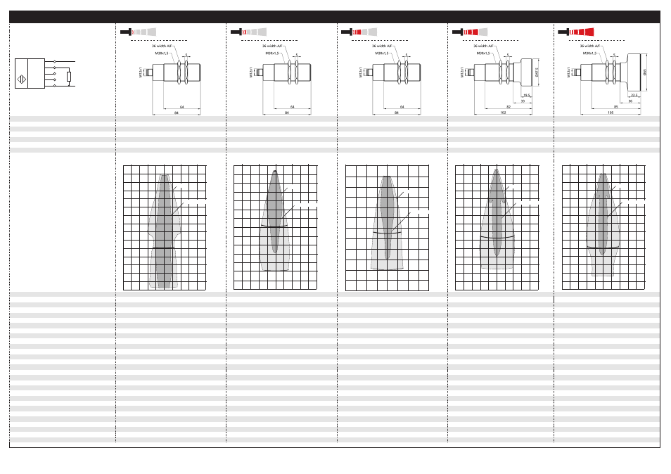
Detection zones
for different objects:
The dark grey areas are determind
with a thin round bar (10 or 27 mm dia.)
and indicate the typical operating range
of a sensor. In order to obtain the light grey
areas, a plate (500 x 500 mm) is introduced
into the beam spread from the side.
In doing so, the optimum angle between
plate and sensor is always employed.
This therefore indicates the maximum
detection zone of the sensor.
It is not possible to evaluate ultrasonic
reflections outside this area.
320 kHz
0,18 mm
400 kHz
0,18 mm
Reproducibility
Accuracy
± 0,15 %
± 1 % (Temperature drift internal compensated,
± 0,15 %
± 1 % (Temperature drift internal compensated,
may be deactivated
1)
, 0,17%/K without compensation)
may be deactivated
1)
(0,17%/K without compensation)
200 kHz
0,18 mm to 0,57 mm, depending on the
120 kHz
0,18 mm to 1,5 mm, depending on the
analogue window
analogue window
80 kHz
0,18 mm to 2,4 mm, depending on the
analogue window
± 0,15 %
± 1 % (Temperature drift internal compensated,
± 0,15 %
± 1 % (Temperature drift internal compensated,
may be deactivated
1)
(0,17%/K without compensation)
may be deactivated
1)
(0,17%/K without compensation)
± 0,15 %
± 1 % (Temperature drift internal compensated,
may be deactivated
1)
(0,17%/K without compensation)
Opperating voltage U
B
Voltage ripple
No-load supply current
Housing
9 V to 30 V DC, reverse polarity protection
±10 %
9 V to 30 V DC, reverse polarity protection
±10 %
≤ 80 mA
Brass sleeve, nickel-plated, plastic parts: PBT;
≤ 80 mA
Brass sleeve, nickel-plated, plastic parts: PBT;
Class of protection to EN 60529
Norm conformity
Ultrasonic transducer: polyurethane foam,
epoxy resin with glass content
Ultrasonic transducer: polyurethane foam,
epoxy resin with glass content
IP 67
EN 60947-5-2
IP 67
EN 60947-5-2
9 V to 30 V DC, reverse polarity protection
±10 %
9 V to 30 V DC, reverse polarity protection
±10 %
≤ 80 mA
Brass sleeve, nickel-plated, plastic parts: PBT;
≤ 80 mA
Brass sleeve, nickel-plated, plastic parts: PBT;
9 V to 30 V DC, reverse polarity protection
±10 %
≤ 80 mA
Brass sleeve, nickel-plated, plastic parts: PBT;
Ultrasonic transducer: polyurethane foam,
epoxy resin with glass content
Ultrasonic transducer: polyurethane foam,
epoxy resin with glass content
IP 67
EN 60947-5-2
IP 67
EN 60947-5-2
Ultrasonic transducer: polyurethane foam,
epoxy resin with glass content
IP 67
EN 60947-5-2
Type of connection
Controls
Indicators
5-pin initiator plug,
Brass, nickel-plated
5-pin initiator plug,
Brass, nickel-plated
Yes, via Com-channel
No
Yes, via Com-channel
No
Programmable
Operating temperature
Storage temperature
Weight
Yes, with Teach-in and LinkControl
-25°C bis +70°C
Yes, with Teach-in and LinkControl
-25°C bis +70°C
-40°C bis +85°C
200 g
-40°C bis +85°C
200 g
5-pin initiator plug,
Brass, nickel-plated
5-pin initiator plug,
Brass, nickel-plated
Yes, via Com-channel
No
Yes, via Com-channel
No
5-pin initiator plug,
Brass, nickel-plated
Yes, via Com-channel
No
Yes, with Teach-in and LinkControl
-25°C bis +70°C
Yes, with Teach-in and LinkControl
-25°C bis +70°C
-40°C bis +85°C
200 g
-40°C bis +85°C
260 g
Yes, with Teach-in and LinkControl
-25°C bis +70°C
-40°C bis +85°C
320 g
Response time
1)
Time delay before availibility
Order No.
32 ms
< 300 ms
64 ms
< 300 ms
mic-25/IU/M
mic-35/IU/M
Current output 4 – 20 mA
Voltage output 0 – 10 V
R
L
≤ 100 Ω at 9 V ≤ U
B
≤ 20 V;
R
L
≤ 500 Ω at U
B
≥ 20 V
R
L
≤ 100 Ω at 9 V ≤ U
B
≤ 20 V;
R
L
≤ 500 Ω at U
B
≥ 20 V
Rising/falling output characteristic
R
L
≥ 100 kΩ at U
B
≥ 15 V, short-circuit-proof
Rising/falling output characteristic
R
L
≥ 100 kΩ at U
B
≥ 15 V, short-circuit-proof
92 ms
< 300 ms
172 ms
< 300 ms
mic-130/IU/M
mic-340/IU/M
240 ms
< 300 ms
mic-600/IU/M
R
L
≤ 100 Ω at 9 V ≤ U
B
≤ 20 V;
R
L
≤ 500 Ω at U
B
≥ 20 V
R
L
≤ 100 Ω at 9 V ≤ U
B
≤ 20 V;
R
L
≤ 500 Ω at U
B
≥ 20 V
Rising/falling output characteristic
R
L
≥ 100 kΩ at U
B
≥ 15 V, short-circuit-proof
Rising/falling output characteristic
R
L
≥ 100 kΩ at U
B
≥ 15 V, short-circuit-proof
R
L
≤ 100 Ω at 9 V ≤ U
B
≤ 20 V;
R
L
≤ 500 Ω at U
B
≥ 20 V
Rising/falling output characteristic
R
L
≥ 100 kΩ at U
B
≥ 15 V, short-circuit-proof
1) Can be programmed with LinkControl
Rising/falling output characteristic
Rising/falling output characteristic
Rising/falling output characteristic
Rising/falling output characteristic
Rising/falling output characteristic
Analogue output
+U
B
-U
B
IU
Com
1
2
4
5
3
U
mic-25…
mic-35…
mic-130…
mic-340…
mic-600…
0 cm
5 cm
10 cm
15 cm
20 cm
25 cm
30 cm
35 cm
Plate
Round bar
ø 10 mm
10 cm
5 cm
0 cm
5 cm
10 cm
0 cm
10 cm
20 cm
30 cm
40 cm
50 cm
60 cm
Plate
Round bar ø 27 mm
20 cm
10 cm
0 cm
10 cm
20 cm
35 cm
0 m
0,4 m
0,8 m
1,2 m
1,6 m
2 m
1,3 m
Plate
Round bar ø 27 mm
0,8 m
0,4 m
0 m
0,4 m
0,8 m
0 m
0,8 m
1,6 m
2,4 m
3,2 m
4 m
4,8 m
5,6 m
3,4 m
Plate
Round bar ø 27 mm
1,6 m
0,8 m
0 m
0,8 m
1,6 m
0 m
1,2 m
2,4 m
3,6 m
4,8 m
6 m
7,2 m
8,4 m
Plate
Rund bar ø 27 mm
2,4 m
1,2 m
0 m
1,2 m
2,4 m
The contents of this document are subject to technical changes. Specifications are presented in a descripted way only. They do not
warrant product features.
microsonic GmbH • Hauert 16 • D-44227 Dortmund • Tel: +49 (0)2 31 / 97 51 51-0 • Fax: +49 (0)2 31 / 97 51 51-51 •E-Mail: [email protected] • www.microsonic.de