Cet™ scale, mte side mount configuration – MicroE CET for MTE Series User Manual
Page 20
Page 20
CET™ Scale, MTE Side Mount Configuration
Installation By Mounted Applicator Tool
3.
Mount the Applicator Tool.
Mount the Applicator Tool in the Side Mount Bracket Kit/Sensor mounting holes. Rotate the knob that controls
the contact cylinder plunger to the UP position (See Step 6.). Use the red spacer (1.00mm) Z-height shim to
set up the approximate Z-height, to ensure proper Applicator Tool function.
4.
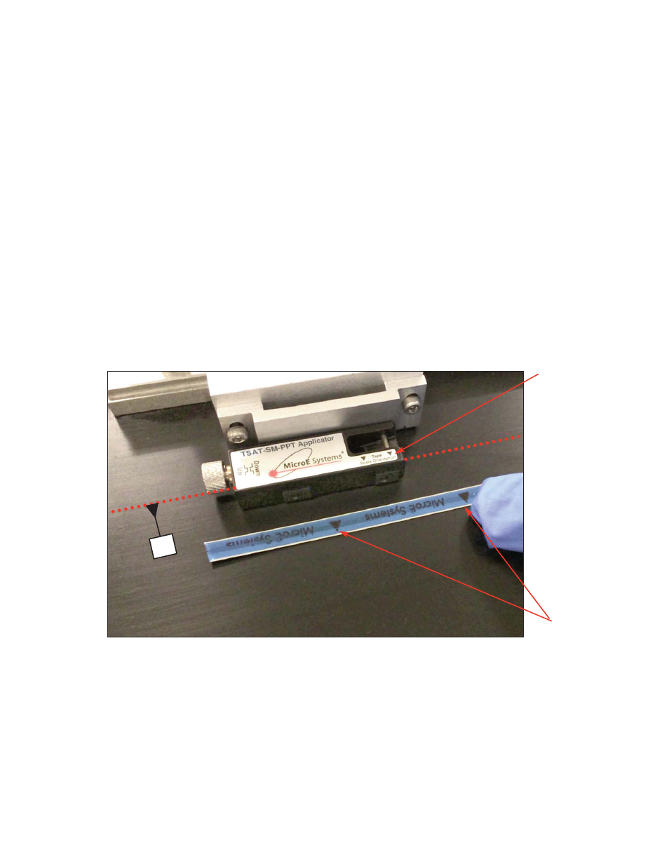
Note tape scale orientation with arrows and the “D” reference edge.
The applicator tool is shown mounted to the MTE/Bracket Kit Adaptor Sensor mount. Both Tape Scale arrows,
and Applicator Tool orientation arrows need to point in the same direction for proper configuration.
Also note, the “D” reference edge is determined from the MTE interface drawing. The tape scale orientation
arrows always point to the “D” reference edge. In the example below, the dotted red line shown is the
measured “D” reference edge. When the tape scale is finally installed, the orientation arrows will be pointing to
the calculated “D” reference edge.
In the example shown, the left side of the tape scale needs to go into the applicator tool entry channel first.
Tape Scale
orientation arrows
Tool orientation
arrows
D