Cet™ scale, mte top mount configuration – MicroE CET for MTE Series User Manual
Page 15
Page 15
CET™ Scale, MTE Top Mount Configuration
Installation By Mounted Applicator Tool
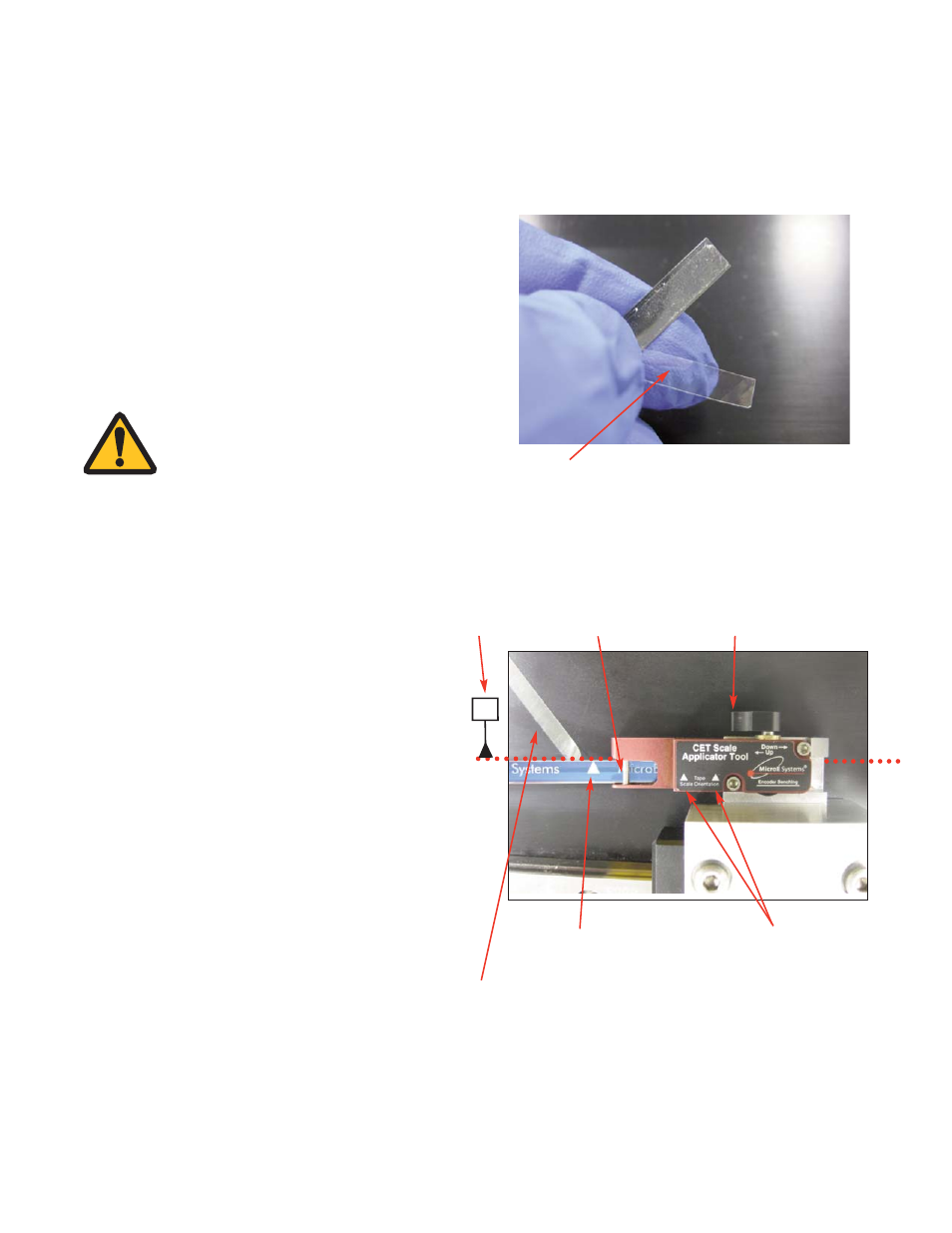
Peel back about 50mm (2 inches) of clear adhesive backer tape.
8.
Tape Scale Insertion
Turn the tool contact cylinder knob to the
UP
position.
Insert the “correct” end of the tape scale into the
applicator tool, making sure the clear backing tape
curls out of the way.
The orientation arrows on the Tape Scale and
Applicator Tool need to point in the same direction.
Also note, the “D” reference edge is determined
from the MTE interface drawing. The tape scale
orientation arrows always point to the “D” reference
edge. In the example, the dotted red line shown is
the measured “D” reference edge. When the tape
scale is finally installed, the orientation arrows will
be pointing to the calculated “D” reference edge.
Clear adhesive backer tape peeled
back about 50mm (2 inches).
Tool contact cylinder in
UP position
Tape slides into channel
under the dowel pin.
Tool orientation arrows
7.
Tape Scale Preparation
Using a sharp tool or fingernail, peel off a short
section of bottom adhesive backing, approximately
50mm (2 inches) from the “correct” end of the scale
to be inserted into the applicator tool.
Take care not to touch the adhesive or allow any
particle contamination.
Tape scale orientation arrows
NOTE:
Do not peel the blue
protective film off at
this time.
D
“D” datum edge
from MTE
interface drawing