Ch 8 - analog i/o module, Pointscan/108, Overview – Measurement Computing PointScan 100 Series rev.1.0 User Manual
Page 29: Wiring, I/o registers, 8 - analog i/o module, Combined analog input and, Output module, Overview -1 wiring -1 i/o registers -1, Analog i/o module 8
PointScan/100 User’s Manual
8-28-01
Analog I/O Modules 8-1
Analog I/O Module
8
This section documents the following module:
PointScan/108
Note:
It is not necessary to recalibrate analog I/O if a logic module is replaced.
Analog logic modules may be hot swapped and will not require recalibration. User calibration data is stored
in system memory outside of the analog module. Factory calibration data is stored in memory in the plug-in
logic module. Since all logic modules are calibrated to the same factory standards, recalibration is not
necessary if logic modules are moved or replaced.
PointScan/108
Combined Analog Input and Output Module
Overview
This module combines eight 4-20 mA analog inputs and four 4-20 mA outputs. More information can be
found in the on-line help supplied with the IO Toolkit program.
Number of Analog Inputs
8 (14 bit resolution)
Input Range
4 - 20 mA
Input Impedance
100 ohms Note: input voltage drop = 2 volts at 20 mA
Number of Analog Outputs
4 (16 bit resolution)
Output Range
4 - 20 mA
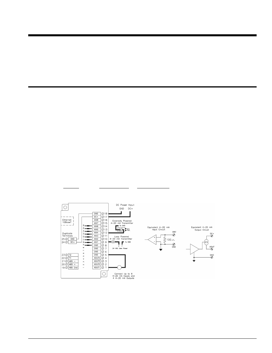
Wiring
A single input terminal is provided for each input and output channel. Care must be taken to externally
provide a suitable instrumentation ground for these input and output circuits.
I/O Registers
Function
IOtech Registers
Modbus Registers
Analog Inputs
AX0 – AX7
30001 – 30008
Analog Outputs
AY0 – AY3
40001 – 40004