Pointscan/109, Overview, Wiring and jumpers – Measurement Computing PointScan 100 Series rev.1.0 User Manual
Page 26: I/o registers, 4 rtd inputs and, 4 discrete inputs, Overview -2 wiring and jumpers -2 i/o registers -2
6-2 Discrete / Analog Modules
9-12-01
PointScan/100 User’s Manual
PointScan/109
4 RTD Inputs and 4 Discrete Inputs
Overview
Four RTD inputs provide 16 bit high resolution analog measurements. Discrete inputs may be wired as all
sourcing or sinking. An input count feature uses analog input registers to accumulate the positive
transitions of each input. More information on this and other features can be found in the on-line help
supplied with the IO Toolkit program.
Number of Channels
4 RTD inputs (16 bit resolution), 4 discrete inputs
RTD Input Type / Range
100 ohm platinum, -200 to 850
°C
Discrete Input Range
12/24 VDC/VAC
Input Current @ 24 VDC
6.7 mA
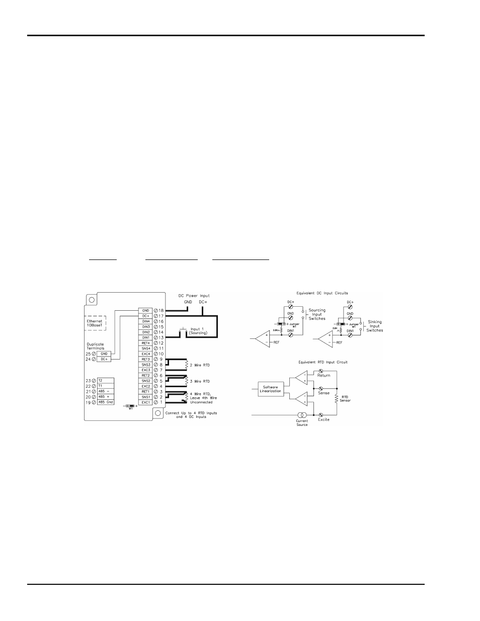
Wiring and Jumpers
See the wiring diagram below for RTD inputs. Discrete inputs need positive DC or AC voltage applied to
an input to indicate an ON condition. All channels are referenced to a common return or supply, which is
connected to the negative side (ground) or positive side (DC+) of the DC power source. One wire from
each sourcing field input should be bussed together and connected to terminal 17 (DC +). One wire from
each sinking field input should be bussed together and connected to terminal 18 (DC GND). Refer to the
wiring diagram below. Set jumper W1 to match the wiring configuration of the discrete inputs
I/O Registers
Function
IOtech Registers
Modbus Registers
RTD Inputs
AX0 – AX3
30001 – 30004
Discrete Inputs
X0 – X3
10001 – 10004
Counter Inputs
AX4 – AX7
30005 – 30008