Pointscan/100 series panel assembly, Pointscan/100 series panel, Assembly -2 – Measurement Computing PointScan 100 Series rev.1.0 User Manual
Page 14
2-2 Ethernet, RS485 Wiring
9-12-01
PointScan/100 User’s Manual
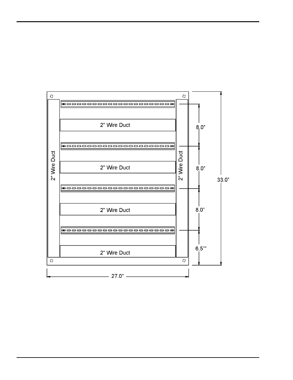
PointScan/100 Series Panel Assembly
PointScan/100 Series I/O snaps onto DIN rail strips fastened to the subpanel. The following figure shows
a sample panel with DIN rail strips and wire duct attached. Recommended DIN rail spacing is 8 inches.
This spacing allows room for wire duct to be installed without obstructing field wiring installation.
The PointScan/100 Series modules are typically installed against one another, but space may be left
between modules to accommodate other DIN rail mounted components such as terminal blocks and fuse
holders. End clamps are recommended to restrict side-to-side movement. The figures on this page and the
next show the physical dimensions of the PointScan/100 Series components.
PointScan/100 Series modules may be installed in any orientation and order on your panel. The modules
are electrically interconnected using RS485 and Ethernet, beginning with the gateway.
Sample Layout For a 36” x 30” Enclosure