Ch 4 - discrete i/o modules, Pointscan/129, Overview – Measurement Computing PointScan 100 Series rev.1.0 User Manual
Page 19: Wiring and jumpers, Tpo feature, 4 - discrete i/o modules, 8 discrete inputs and, 8 discrete outputs, Overview -1 wiring and jumpers -1 tpo feature -1, Discrete i/o modules 4
PointScan/100 User’s Manual
9-12-01
Discrete I/O Modules 4-1
Discrete I/O Modules
4
This section documents the following modules
PointScan/129, PointScan/122, PointScan/127
PointScan/129
8 Discrete Inputs and 8 Discrete Outputs
Overview
This module provides one terminal for each input or output channel. All inputs may be wired as sourcing or
sinking. Outputs are wired in a sourcing (power switching) configuration only. An input count feature uses
analog input registers to accumulate the positive transitions of each input. More information can be found
in the on-line help in the IO Toolkit program.
Number of Channels
8 discrete inputs, 8 discrete outputs (PointScan/129 only)
Input Voltage Range
12/24 VDC/VAC
Input Current @ 24 VDC
6.7 mA
Output Voltage Range
10 – 30 VDC
Maximum Count Rate
100 Hz (6000 / minute) each input, plus selectable 2KHz (120,000 /
minute) mode for input 1 only
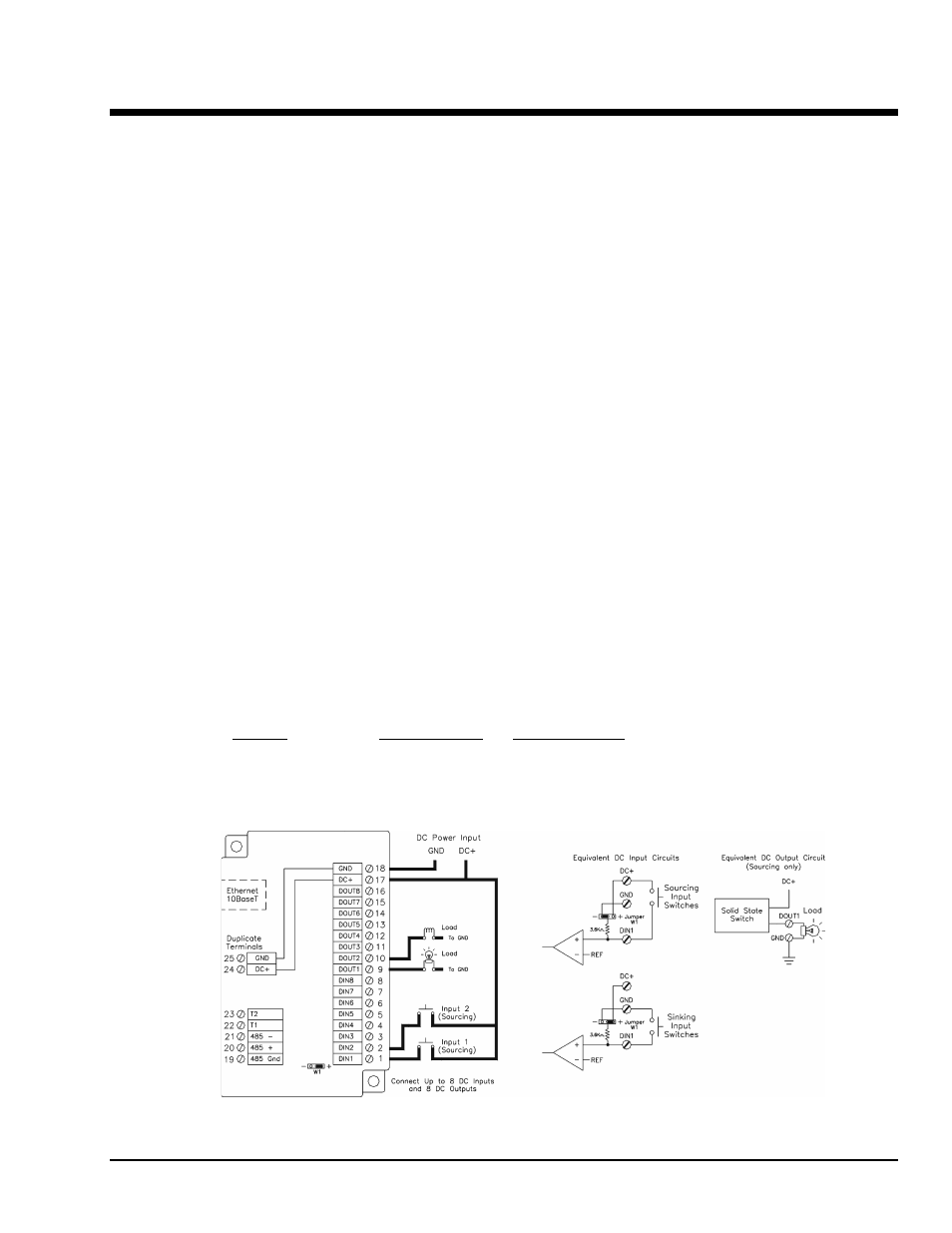
Wiring and Jumpers
One wire from each sourcing field input should be bussed together and connected to terminal
17 (DC +). One wire from each sourcing field output and/or or sinking field input should be bussed
together and connected to terminal 18 (DC GND). Refer to the wiring diagram below. Set jumper W1 to
match the wiring configuration of the inputs.
TPO Feature
Time proportioned outputs pulse ON and OFF with a duty cycle proportional to an analog value stored in
an analog output register. TPO outputs are a low cost way to get smooth proportional control of heaters and
other process variables. Typically, TPO analog output registers are assigned to the output of PID or other
control program. Use the IO Toolkit to set pulse cycling as fast as
10 mS or as slow (many minutes) as your system dynamics require. Each output may be configured as a
TPO or ordinary discrete output. I/O Registers
Function
IOtech Registers
Modbus Registers
Discrete Inputs
X0 – X7
10001 – 10008
Discrete Outputs
Y0 – Y7
00001 – 00008
TPO Values
AY0 – AY7
40001 – 40008
Counter Inputs
AX0 – AX7
30001 – 30008