Pointscan/127, Overview, Input wiring – Measurement Computing PointScan 100 Series rev.1.0 User Manual
Page 21: I/o registers, High speed counter, Module, Overview -3 input wiring -3 i/o registers -3
PointScan/100 User’s Manual
9-12-01
Discrete I/O Modules 4-3
PointScan/127
High Speed Counter Module
Overview
This high-speed counter module has eight isolated circuits that accept pulse inputs from a variety of
sources, including quadrature and incremental encoders. Count values are reported in 16 bit analog input
registers or 32 bit long registers. The states of the counter inputs are also reported as discrete inputs. Pulse
rates up to 50 kHz are supported. The counters can be reset by toggling discrete output bits. Counter modes
are selected using the IO Toolkit program. More information on this and other features can be found in the
on-line help supplied with the IO Toolkit program.
Number of Channels
8 discrete inputs, isolated
Input Voltage Range
12/24 VDC/VAC
Input Current @ 24 VDC
6.7 mA
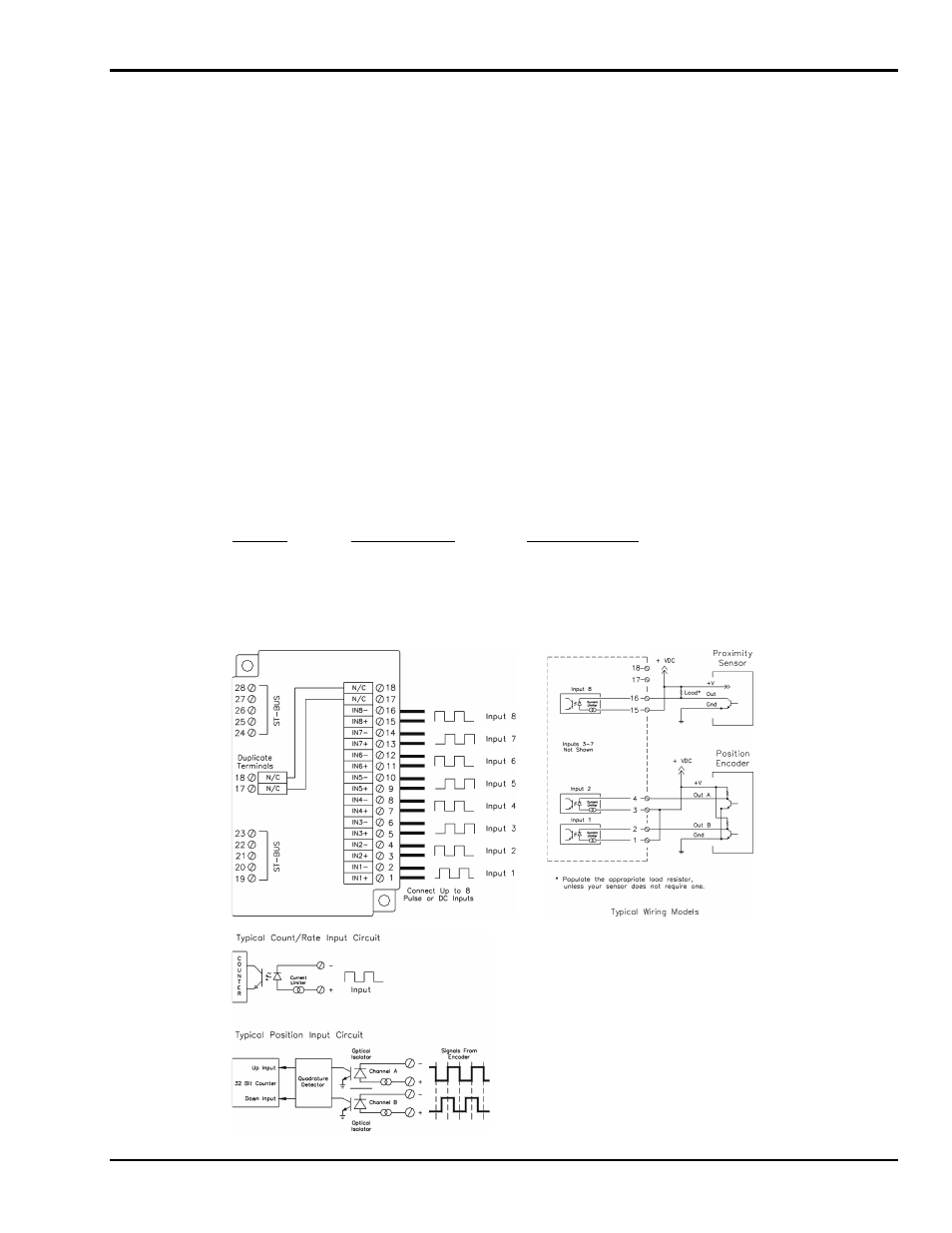
Input Wiring
Screw terminal assignments are shown below. For best noise immunity, connect input signals using twisted
wire pairs. To maintain the best differential noise rejection, do not connect
(-) screw terminals together at the I/O base. Positive DC voltage must be applied to an input to indicate an
ON condition. Refer to the wiring diagram below.
Any odd-numbered input can be gated by connecting a gating signal to the next highest even-numbered
input. For example, Input 2 can gate the counter for Input 1.
I/O Registers
Function
IOtech Registers
Modbus Registers
Discrete Inputs
X0 – X7
10001 – 10008
Counter Inputs
AX0 – AX7 or LI0 – LI7
30001 – 30008
35001 – 35008
Resets
Y0 – Y7
00001 – 00008