Dbk identification tables, Analog output dbks, Digital i/o control dbks – Measurement Computing DaqBoard-ISA User Manual
Page 33: Analog signal conditioning dbks
Daq Systems
02-13-02
DBK Basics, pg. 5
DBK Identification Tables
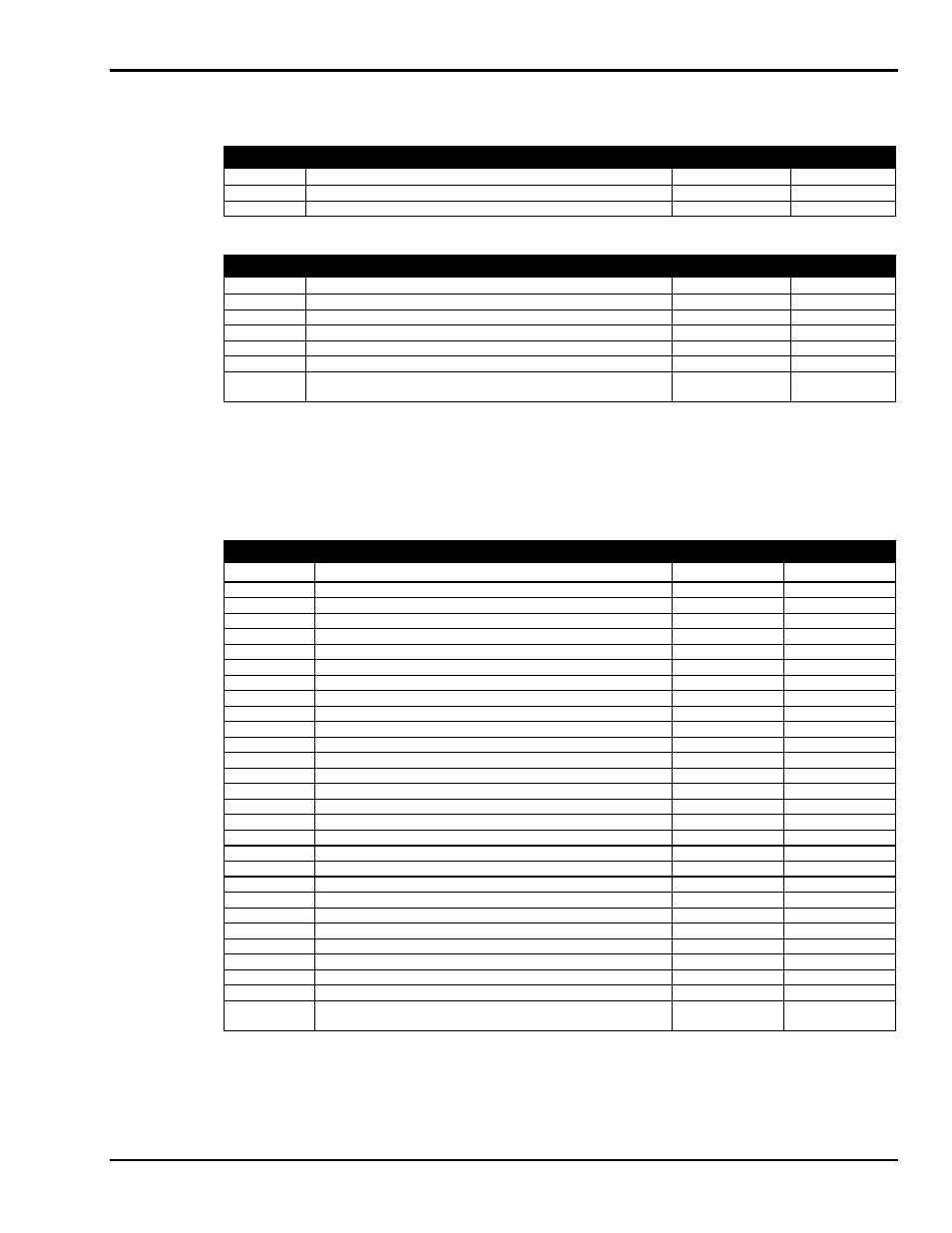
Analog Output DBKs
Analog Output
Product
Name/Description
I/O
Conectivity
DBK2
Voltage Output Card
4 channels
P1
DBK5
Current Output Card
4 channels
P1
Digital I/O Control DBKs
Digital I/O / Control
Product
Name/Description
I/O
Conectivity
DBK20
General-Purpose Digital I/O Card (Screw Terminals)
48 channels
P2
DBK21
General-Purpose Digital I/O Card (DB37 Connectors)
48 channels
P2
DBK23
Optically Isolated Digital-Input Module
24 channels
P2
DBK24
Optically Isolated Digital-Output Module
24 channels
P2
DBK25
Relay Output Card
8 channels
P2
DBK208
Carrier board for Opto-22 Compatible Solid-State-Relay
Digital Modules.
Two 8-bit banks of
SSR modules
Two P2s
P4
Analog Signal Conditioning DBKs
The DBKs that are used for analog signal conditioning attach to transducers and condition their outputs into
analog voltages. An A/D converter, located in the primary acquisition device, measures the analog
voltages. There are many signal-conditioning solutions available (and more are in development). Note that
DBK high-capacity modules require more circuitry than can fit on a compact card.
Analog Signal Conditioning
Product
Name/Description
I/O
Connectivity
1
DBK4
Dynamic Signal Input Card
2 channels
P1
DBK7
Frequency-to-Voltage Input Card
4 channels
P1
DBK8
High-Voltage Input Card
8 channels
P1
DBK9
RTD Measurement Card
8 channels
P1
DBK12
Low-Gain Analog Multiplexing Card
Note 2
16 channels
P1
DBK13
High-Gain Analog Multiplexing Card
Note 2
16 channels
P1
DBK15
Universal Current/Voltage Input Card
Note 2
16 channels
P1
DBK16
Strain-Gage Measurement Card
2 channels
P1
DBK17
Simultaneous Sample & Hold Card
4 channels
P1
DBK18
Low-Pass Filter Card
4 channels
P1
DBK19
Thermocouple Card
Note 2
14 channels
P1
DBK42
5B Isolated Signal-Conditioning Module
16 channels
P1
DBK43A
Strain-Gage Measurement Module
8 channels
P1
DBK44
5B Isolated Signal-Conditioning Card
2 channels
P1
DBK45
SSH and Low-Pass Filter Card
4 channels
P1
DBK50
Isolated High-Voltage Input Module
8 channels
P1
DBK51
Isolated Low-Voltage Input Module
8 channels
P1
DBK52
Thermocouple Input Module
Note 2
14 channels
P1
DBK53
Low-Gain Analog Multiplexing Module
Note 2
16 channels
P1
DBK54
High-Gain Analog Multiplexing Module
Note 2
16 channels
P1
DBK70
Vehicle Network Interface, Analog Multiplexer Module
16 channels
P1
DBK80
Differential Voltage Input Card with Excitation Output
16 channels
P1
DBK81
Thermocouple Card, High-Accuracy
7 channels
P1
DBK82
Thermocouple Card, High-Accuracy
14 channels
P1
DBK83
Thermal Couple Card, High-Accuracy; uses Connection Pod
14 channels
POD-1
DBK84
Thermocouple Module, High-Accuracy
14 channels
P1
DBK207
Carrier Board for 5B Compatible Analog Input Modules
16 channels
Two P1s / P4
DBK207/CJC
Carrier Board for 5B Compatible Analog Input Modules.
DBK207/CJC includes cold junction compensation (CJC)
16 channels
Two P1s / P4
Note 1:
P1, P2, and P3 DB37 connectors do not exist on the DaqBoard/2000 Series or /2000c Series boards,
but are obtained by using P4 adapters (DBK200 series). These adapters typically connect to the
DaqBoard/2000 Series [/2000c Series] 100-pin P4 connector via a CA-195 cable.
Note 2:
For DaqBoard/2000 and cPCI DaqBoard/2000 Series boards, internal clocks should be set to 100 kHz
when used with any of the following DBK options:
DBK12
,
DBK13
,
DBK15
,
DBK19
,
DBK52
,
DBK53
,
and
DBK54
. See specific DBK section for details.