P2, db37 pinout, digital i/o …… 3-8, P2, db37 pinout, digital i/o – Measurement Computing DaqBoard-ISA User Manual
Page 26
3-8 Hardware
02-14-02
DaqBoard-ISA User’s Manual
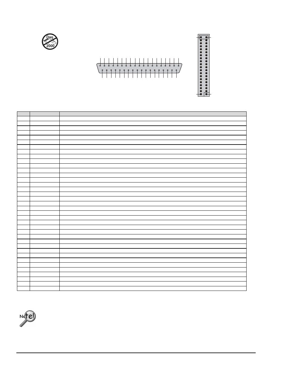
P2,
DB37 Pinout
Digital I/O Connections for ISA-Type DaqBoards
The DaqBoard [ISA-Type] P2
interface is available on:
DaqBoard/100A
DaqBoard/200A
1
9
G
N
D
P
O
R
T
A
0
3
7
P
O
R
T
A
1
3
6
P
O
R
T
A
2
3
5
P
O
R
T
A
3
3
4
P
O
R
T
A
4
3
3
P
O
R
T
A
5
3
2
P
O
R
T
A
6
3
1
P
O
R
T
A
7
3
0
P
O
R
T
C
0
2
9
P
O
R
T
C
1
2
8
P
O
R
T
C
2
2
7
P
O
R
T
C
3
2
6
P
O
R
T
C
4
2
5
P
O
R
T
C
5
2
4
P
O
R
T
C
6
2
3
P
O
R
T
C
7
2
2
G
N
D
2
1
+
5
V
2
0
8
P
O
R
T
B
2
7
P
O
R
T
B
3
6
P
O
R
T
B
4
5
P
O
R
T
B
5
4
P
O
R
T
B
6
3
P
O
R
T
B
7
2
I
R
E
N
A
B
L
E
1
IR
I
N
P
U
T
1
0
P
O
R
T
B
0
9
P
O
R
T
B
1
1
8
+
5
1
7
G
N
D
1
6
N
/C
1
5
G
N
D
1
4
N
/C
1
3
G
N
D
1
2
N
/C
11
G
N
D
1
39
40
2
T he P 2 40 -p in h eader d oes not
hav e a direc t pin-to-pin co rrelation
w ith the P 2 D B 37 con nec tor.
D B 37 C on nec tor via C A -6 0 Inte rfa ce C able
Pin
Signal Name
Description for P2 Pin Use
1
IR INPUT
Interrupt line input (no functions to access this)
2
IR ENABLE
Interrupt line enable (no functions to access this)
3
PORT B 7
Digital input/output - port B bit 7
4
PORT B 6
Digital input/output - port B bit 6
5
PORT B 5
Digital input/output - port B bit 5
6
PORT B 4
Digital input/output - port B bit 4
7
PORT B 3
Digital input/output - port B bit 3
8
PORT B 2
Digital input/output - port B bit 2
9
PORT B 1
Digital input/output - port B bit 1
10
PORT B 0
Digital input/output - port B bit 0
11
GND
Digital ground
12
N/C
Pin not connected/not used
13
GND
Digital ground
14
N/C
Pin not connected/not used
15
GND
Digital ground
16
N/C
Pin not connected/not used
17
GND
Digital ground
18
+5 V
+5 V supply (Refer to
Power Management
, in the DBK manual).
19
GND
Digital ground
20
+5 V
+5 V supply (Refer to
Power Management,
in the DBK manual).
21
GND
Digital ground
22
PORT C 7
Digital input/output - port C bit 7
23
PORT C 6
Digital input/output - port C bit 6
24
PORT C 5
Digital input/output - port C bit 5
25
PORT C 4
Digital input/output - port C bit 4
26
PORT C 3
Digital input/output - port C bit 3
27
PORT C 2
Digital input/output - port C bit 2
28
PORT C 1
Digital input/output - port C bit 1
29
PORT C 0
Digital input/output - port C bit 0
30
PORT A 7
Digital input/output - port A bit 7
31
PORT A 6
Digital input/output - port A bit 6
32
PORT A 5
Digital input/output - port A bit 5
33
PORT A 4
Digital input/output - port A bit 4
34
PORT A 3
Digital input/output - port A bit 3
35
PORT A 2
Digital input/output - port A bit 2
36
PORT A 1
Digital input/output - port A bit 1
37
PORT A 0
Digital input/output - port A bit 0
Note: No local lines are available if digital expansion cards are in use.
.
P2 expansion cables must be kept relatively short to ensure reliable operation.
Do not exceed 14 inches per attached DBK card.
Note: The pinout is for ISA-type DaqBoards. It does not apply to PCI or cPCI type DaqBoards.