Jp1 - external analog expansion power, Configure the isa-daqboard ……2-2, 1) configure the isa-daqboard – Measurement Computing DaqBoard-ISA User Manual
Page 14
2-2 Setup and Startup
02-10-02
DaqBoard-ISA User’s Manual
(1) Configure the ISA-DaqBoard
(Set Jumpers and Configure the DIP-Switch)
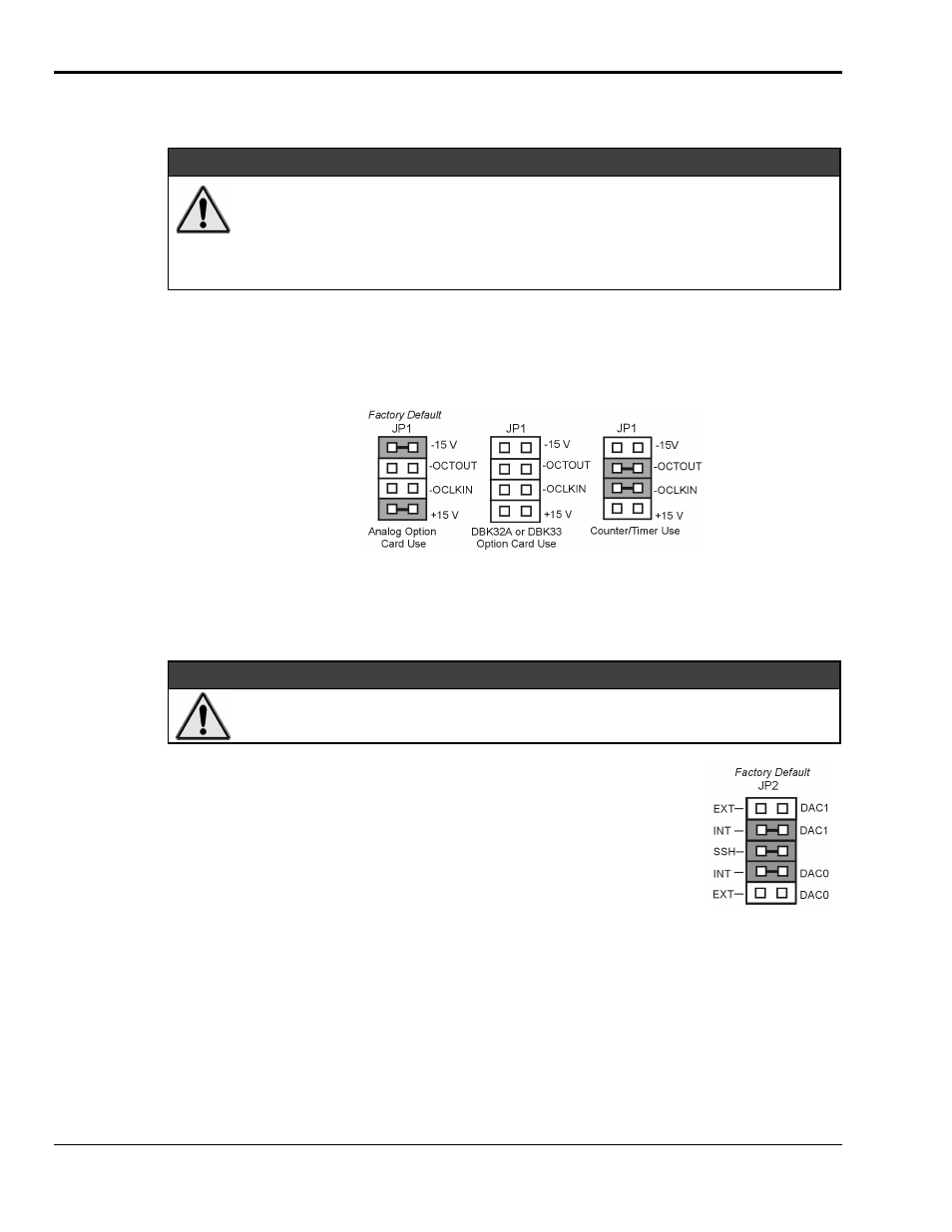
JP1 - External Analog Expansion Power
&$87,21
Placing the jumpers on JP1’s OCTOUT and –OCLKIN could damage the 8254 timer
chip! If either a DBK32A Auxiliary Power Supply or a DBK33 Triple-Output Power
Supply Card is used, the JP1 shunt jumpers must be removed, otherwise timer chip
damage will occur. Refer to the DBK32A, DBK33, and Power Management sections of
the user documentation for more information.
If analog option cards (DBKs) are used, JP1 jumpers are set to provide +15 and -15 VDC to the cards.
If using a DBK32A or DBK33 Power Supply Card, remove all jumpers from JP1.
If no cards are being used, the counter/timer CTR0 is available, and JP1 must be set as shown in the figure.
JP1 Configurations
JP2 - DAC Reference Voltage and SSH (Simultaneous Sample and Hold)
&$87,21
In regard to JP2, the SSH jumper must be removed if you are using EXT DAC0 or EXT
DAC1. See the user’s manual for details.
JP2 selects an Internal (default) or External reference voltage for the two separate
analog outputs.
JP2 also selects SSH (default) for applications using one or more of the following:
DBK2, DBK4, DBK5, DBK7, DBK17, DBK50, or DBK51.
We recommend that you leave the JP2 jumpers at their factory default setting
(see figure at right). Refer to the JP2 material in chapter 3 prior to making
changes.
JP7 – Calibration
Leave JP7 in the default position. Only use JP7 during calibration.