Switches and jumpers, Base address (sw1), Switches and jumpers …… 3-3 – Measurement Computing DaqBoard-ISA User Manual
Page 21: Base address (sw1) …… 3-3
DaqBoard-ISA User’s Manual
02-14-02
Hardware 3-3
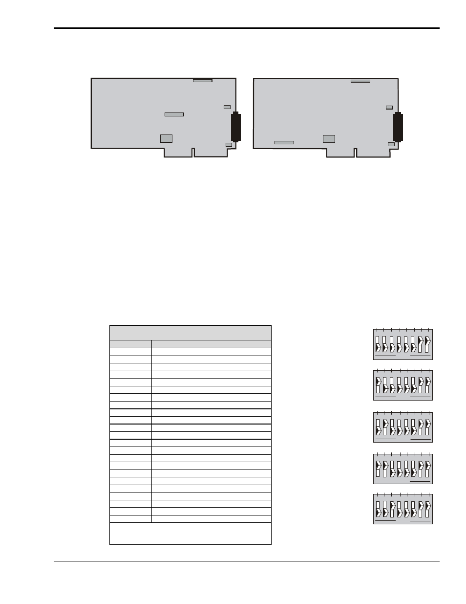
Switches and Jumpers
To ensure that the desired mode of operation is obtained, the ISA-type DaqBoards must be configured.
This is accomplished via on-board jumpers and a DIP-switch. Although the configuration of all four
DaqBoard-ISA models is similar, jumper locations differ, as can be seen in the following figures.
JP 8
S W 1
S W 1
JP 7
JP 7
JP 8
JP 2
JP 2
JP 1
JP 1
0
1
0
1
Base Address
Base Address
D a qB o ard/1 00 A /112 A M othe rbo a rd
D a qB o ard/2 00 A /21 6A M o th erb oa rd
Location of DaqBoard Jumpers
The following DIP-switch and jumpers must be properly set to ensure the desired mode of operation:
• SW1 - Base Address
• JP1 - External Analog Expansion Power
• JP2 - DAC Voltage Reference Header
• JP7 –Reserved for factory use.
• JP8 - Interrupt & DMA
Base Address (SW1)
The computer must know the DaqBoard’s base address. Check the base address setting (3-digit hex) on
SW1, the Base Address switch. The factory default is 300 hex (within the standard range for a prototype
card; see table). If the default value does not work, you must select an address within 200 to 3FF (256 to
1023 decimal). In addition, the address must be on a 4-byte boundary, and it must not conflict with
addresses already in use.
Industry Standard I/O Addresses
Note: Systems vary. This is only a guide.
Hex Range
Device
000-1FF
Internal system
200-207
Game I/O
20C-20D
Reserved
21F
Reserved
278-27F
Parallel printer port 2
2B0-2DF
Alternate enhanced graphics adapter
2E1
GPIB (Adapter 0)
2E2 & 2E3
Data acquisition (Adapter 0)
2F8-2FF
Serial port 2
300-31F
Prototype card
360-363
PC network (low address)
364-367
Reserved
368-36B
PC network (high address)
36C-36F
Reserved
378-37F
Parallel printer port 1
380-38F
SDLC, bisynchronous 2
390-393
Reserved
3A0-3AF
Bisynchronous 1
3B0-3BF
Monochrome display and printer adapter
3C0-3CF
Enhanced graphics adapter
3D0-3DF
Color/Graphics monitor adapter
3F0-3F7
Diskette Controller
3F8-3FF
Serial port 1
Note: I/O addresses, hex 000 to 0FF, are reserved for
the system board I/O. Hex 100 to 3FF are available on
the I/O channel.
304
308
30C
310
300
Fa ctory
D e fau lt
0
1
6 7 8
5
2 3
1
4
O P E N
A2 A3 A4 A5 A6 A7 A8 A9
0
1
6 7 8
5
2 3
1
4
O P E N
A2 A3 A4 A5 A6 A7 A8 A9
0
1
6 7 8
5
2 3
1
4
O P E N
A2 A3 A4 A5 A6 A7 A8 A9
0
1
6 7 8
5
2 3
1
4
O P E N
A2 A3 A4 A5 A6 A7 A8 A9
0
1
6 7 8
5
2 3
1
4
O P E N
A2 A3 A4 A5 A6 A7 A8 A9
Sample Base Addresses
on SW1