Led indicators, Usb connector, Counter i/o and gating – Measurement Computing USB-CTR04 User Manual
Page 8
USB-CTR04 User's Guide
Functional Details
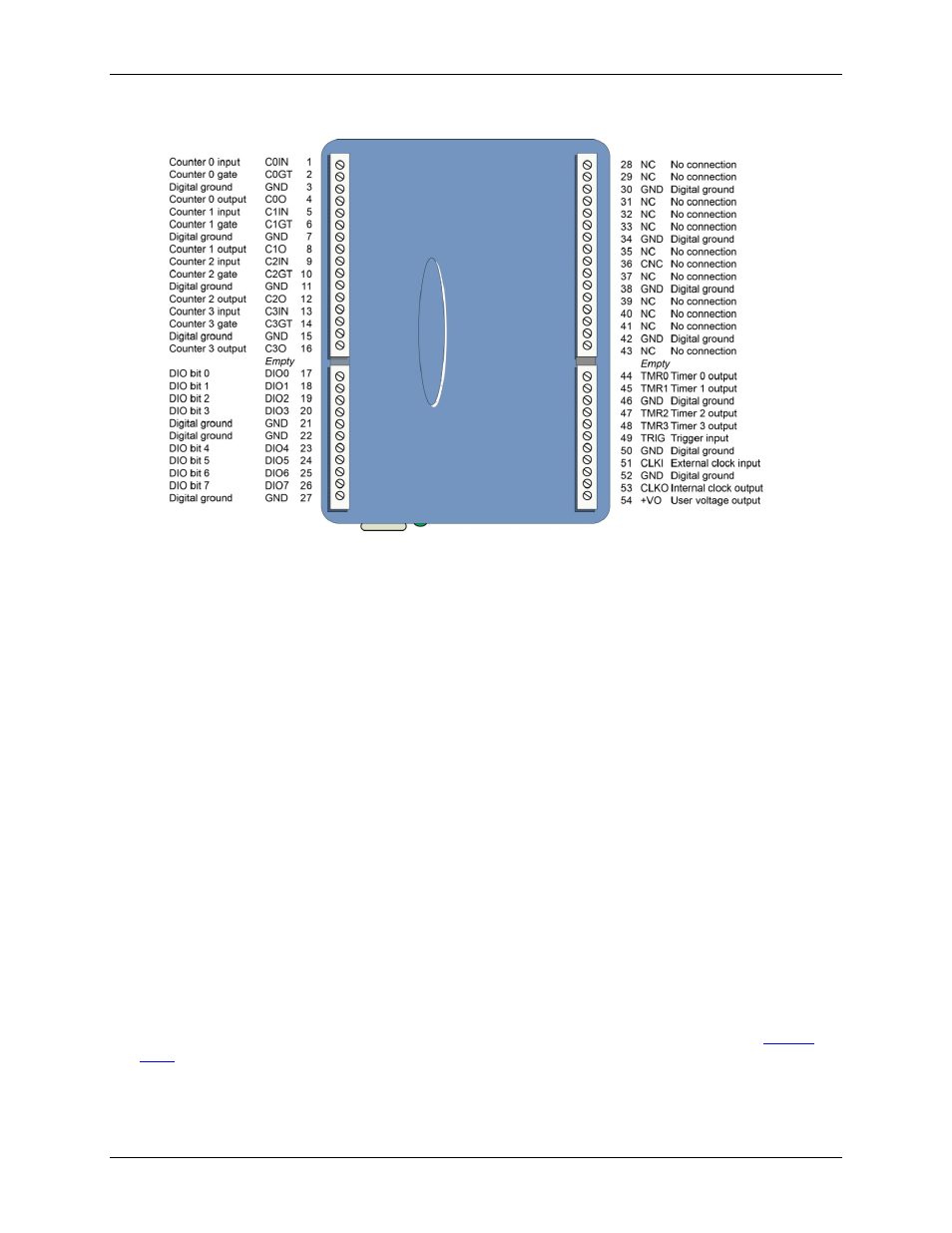
The USB-CTR04 pinout is shown in Figure 3.
Figure 3. USB-CTR04 pinout
LED indicators
The device has two LED indicators –
Status
and
Activity.
The
Status
LED (top) turns on when the device is detected and installed on the computer.
The
Activity
LED (bottom) blinks when data is transferred, and is off otherwise.
Refer to Figure 2 on page 7 for the location of these LEDs.
USB connector
The USB connector provides 5 V power and communication.
Counter I/O and gating
The USB-CTR04 has a counter input (
CxIN
), counter output (
CxO
), counter gate (
CxGT
) screw terminal for
each of its four counter channels.
Counter inputs can be read asynchronously under program control, or synchronously as part of a digital scan
group. In both cases, you can configure counters so that they:
get set to 0 after each read
count up or down and then roll over at a user-set limit
count until the user-set limit has been reached.
Counter inputs can concurrently monitor time periods, frequencies, pulses, and other event-driven incremental
occurrences directly from pulse-generators, limit switches, proximity switches, and magnetic pick-ups.
Counter outputs can be used to control or transmit signals to external devices, and also to
USB-CTR04 counter inputs, counter gates, or digital inputs. Counter outputs are commonly used in
Counter gates use input signals to clear a counter, change counter direction, or start/stop counting. Gate options
are software-selectable and are available when counting in Totalize mode.
8