Specifications, Counter, Chapter 4 – Measurement Computing USB-CTR04 User Manual
Page 19
Chapter 4
Specifications
All specifications are subject to change without notice.
Typical for 25°C unless otherwise specified.
Specifications in italic text are guaranteed by design.
Counter
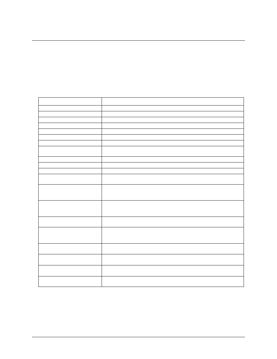
Table 1. Counter specifications
Parameter
Specification
Counter type
FPGA
Counters
4 (each with a corresponding Input, Gate, and Output)
Counter input modes
Totalize, Pulse width, Period, Timing
Mode options
Non-Recycle, Range Limit, Clear on Read, Up/Down,
Gate options
Clear|Reload, Direction Control, Gate, Count trigger; mode dependent
Resolution
Up to 64-bits (software-selectable)
Maximum input frequency
48 MHz
Debounce times
16 steps from 500 ns to 25.5 ms; positive or negative edge sensitive; glitch detect
mode or debounce mode; software-selectable.
Timebase and accuracy
96 MHz (24 MHz – 30 ppm with a 4x DLL (delay-locked loop))
Counter read pacer
Internal or external scan pacer up to 4 MHz
Period/pulse width resolution
20.83 ns; 208.3 ns; 2.083 µs; or 20.83 µs
Input type (C0IN to C3IN and
C0GT to C3GT)
Schmitt trigger, 47 kΩ pull-down to ground with 33 Ω in series
Schmitt trigger hysteresis (C0IN to
C3IN and C0GT to C3GT)
0.76 V typ
0.4 V min
1.2 V max
Input high voltage threshold (C0IN
to C3IN and C0GT to C3GT)
1.74 V typ
1.3 V min
2.2 V max
Input high voltage limit (C0IN to
C3IN and C0GT to C3GT)
5.5 V absolute max
Input low voltage threshold (C0IN
to C3IN and C0GT to C3GT)
0.98 V typ
0.6 V min
1.5 V max
Input low voltage limit (C0IN to
C3IN and C0GT to C3GT)
–0.5 V absolute min
0 V recommended min
Output high voltage
4.4 V min (IOH = –50 µA)
3.76 V min (IOH = –24 mA)
Output low voltage
0.1 V max (IOL = 50 µA)
0.44 V max (IOL = 24 mA)
Output current
24 mA max per pin, constrained to 240 mA across all output pins (counter outputs,
timer outputs, digital outputs, pacer clock output, and +VO)
19