Debounce filters, Trigger after stable mode – Measurement Computing USB-CTR04 User Manual
Page 12
USB-CTR04 User's Guide
Functional Details
If the counter read period is faster than the than the occurrence of the next time-frame rate (available on the
two channels), then some time frames repeat in the acquisition. The bigger the difference between the
counter read period and the time frame occurrence, the more time frames are repeated.
If the counter read period is slower than the time-frame occurrence, then the acquisition misses some time
frames. The bigger the difference between the counter read period and the time frame occurrence, the more
time frames are missed.
Decrease the counter read period in order to capture more time frames.
The data returned is interpreted as time measured in ticks. This data represents the number of tick size intervals
counted during the timing measurement.
Timing mode tick size options are software-selectable. The tick size is a fundamental unit of time derived from
the period of the 96 MHz system clock.
Four counter channel tick sizes are available – 20.83 ns, 208.3 ns, 2083.3 ns, and 20833.3 ns.
Debounce filters
The USB-CTR04 has debounce circuitry which eliminates switch-induced transients that are typically
associated with electro-mechanical devices including relays, proximity switches, and encoders.
All debounce filter options are software-selectable. You can select a debounce time, debounce mode, and rising-
edge or falling-edge sensitivity. Each channel can be debounced with 16 programmable debounce times in the
range of 500 ns to 25.5 ms.
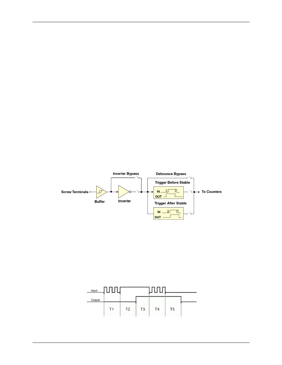
Two debounce filter modes (trigger after stable and trigger before stable) and a debounce bypass are shown in
Figure 5. The signal from the buffer can be inverted before it enters the debounce circuitry. The inverter is used
to make the input rising-edge or falling-edge sensitive.
Figure 5. Debounce block diagram
Edge selection is available with or without debounce. In this case, the debounce time setting is ignored and the
input signal goes straight from the inverter or inverter bypass to the counter module.
The two debounce filter modes are trigger after stable and trigger before stable. In either mode, the selected
debounce time determines how fast the signal can change and still be recognized.
Trigger after stable mode
In the trigger after stable mode, the output of the debounce module does not change state until a period of
stability has been achieved. This means that the input has an edge, and then must be stable for a period of time
equal to the debounce time. Refer to Figure 6.
Figure 6. Trigger after stable mode
12